Welcome to Laser Pointer Forums - discuss green laser pointers, blue laser pointers, and all types of lasers

Buy Site Supporter Role (remove some ads) | LPF Donations

Links below open in new window

FrozenGate by Avery

A Peek into Ryan's Builds: Heatsinking a Hot Linear Driver

Joined
Feb 18, 2012
Messages
796
Points
28
Hey guys,

We all know how hot linear drivers can get sometimes, especially when ran at such a high current as 1.8A. Today I'll be showing you how I heatsink these hot linears :eg:

So let's cut to the chase.


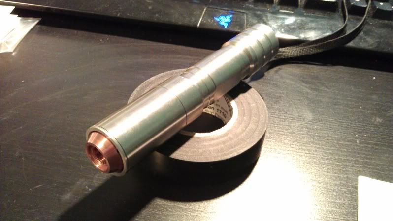
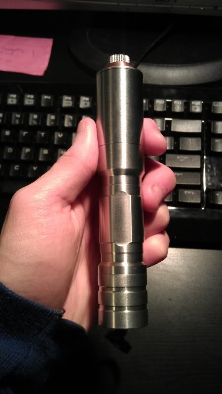
Here is a customer's build I finished yesterday:
IMAG0287.jpg


Walk with me as I prep the driver...

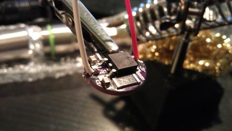
Solder the leads on:
IMAG0266.jpg


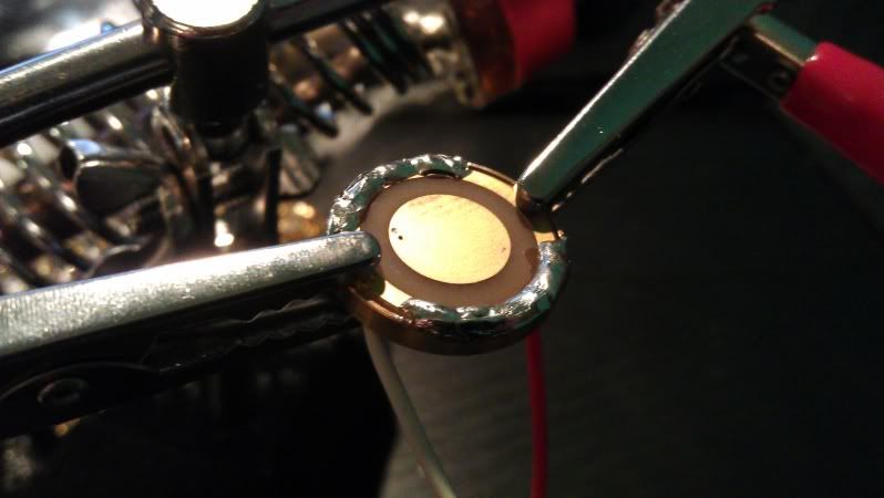
Solder the brass retaining ring to the driver for a good negative ground:
IMAG0267.jpg

IMAG0268.jpg


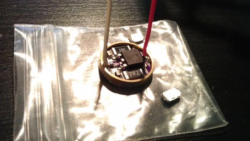
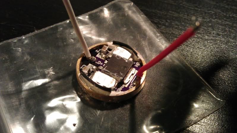
Heatsink the resistors with aluminum fins using non-conductive, non-capacitative Arctic Silver Ceramique 2 thermal compound, then electrically isolate "high-risk" zones with electrical tape for extra precaution against short circuit:
IMAG0269.jpg


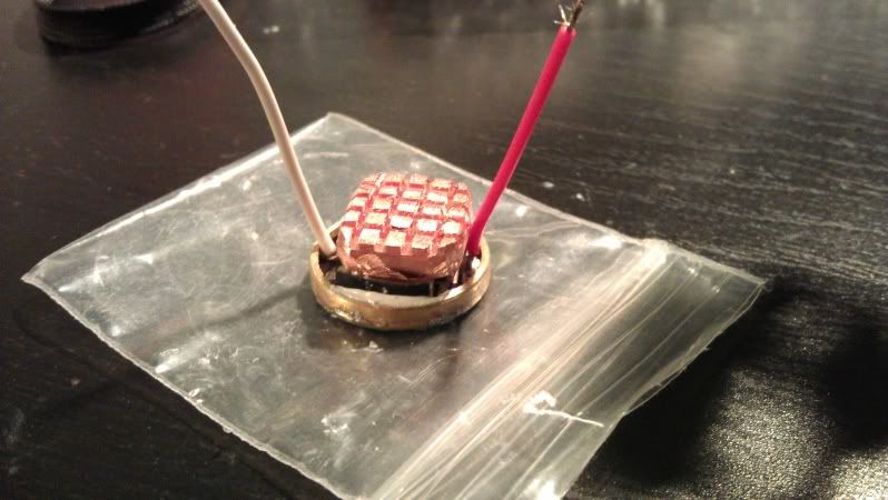
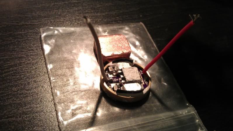
Prepped the IC for mounting a finned copper heatsink, which needs to be ground down in the corners and height to fit in the pill:
IMAG0271.jpg

IMAG0272.jpg


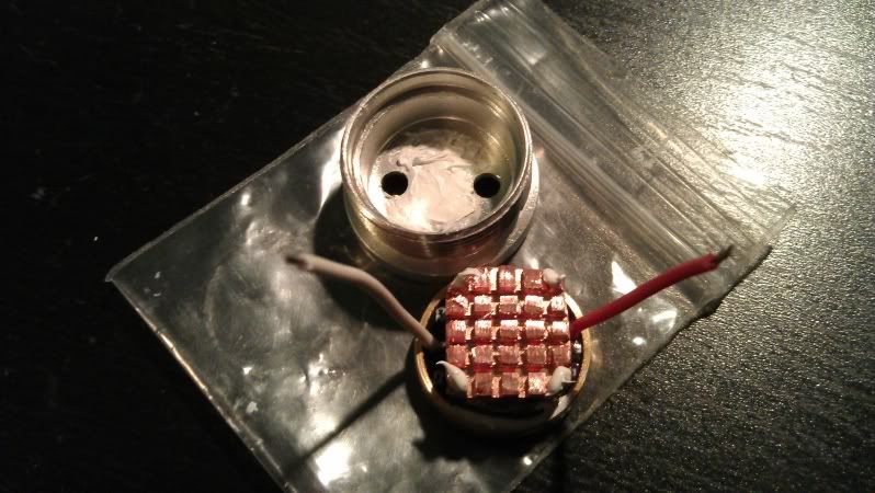
Then prep the underside of the pill & corners of the copper heatsink with thermal compound as the heatsink will press against the pill:
IMAG0273.jpg


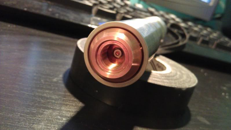
Everything else is fitted together, spread thermal compound along the module then slide it in the heatsink
IMAG0275.jpg

IMAG0276.jpg


For maximum heatsinking effect: prep the underside of the large copper heatsink with thermal compound as it will press against the top of the pill when installed.

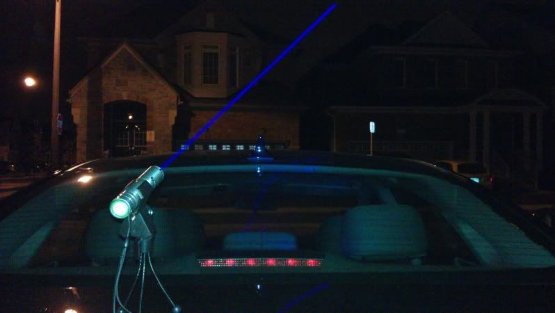
Then enjoy the beam..
IMAG0290.jpg


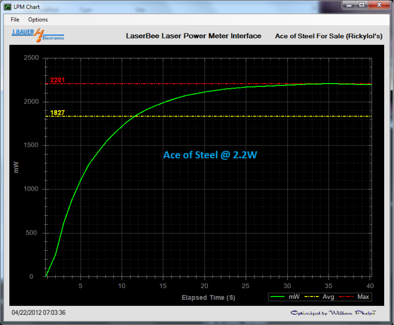
& results.
AceofSteelForSaleLPMChart.png


I was able to run this laser for over 3 minutes w/o thermal protection kicking in and the host just beginning to get uncomfortably warm. I could probably run it longer but I didn't want to go any further.

Hope this helps anyone deal with these hot linears better :beer:

Ryan
 
Last edited:


that's pretty sweet heat sinking.

one note: the newest batch of drivers i ordered, i increased the diameter of the driver to 17mm instead of 16mm.
Now they press fit into the brass ring as well.

Since they fit so nicely, you can now just solder the brass ring to the LD- pad on the other side of the pill.
It makes it look a lot nicer since you don't have to solder all around the other side to hold it into place.
and they fit snug enough into the brass ring you don't have to worry about driver driver shifting around at all.

ty ty :D Ah that's a lot better than trying to jump the little gap with lots of solder. Are those same boards on sale 17mm or are they currently or in transit?

Nice work :beer: looks very well heatsinked to me

Thanks AnthoT ;)
 
Last edited:
Looks good. The key is the thermal contact with the pill which will move the heat into the host body. That setup should do very with the copper mounted on the pill.:beer:
 
Last edited:
Its a really nice driver.

I bet the guy who designed it is a stud :whistle:
 
Its a really nice driver.

I bet the guy who designed it is a stud :whistle:
Probably some cocky high school kid :D

Ryan, the ones for sale are in transit, and are the 17mm.
Any round drivers ordered in the past 2 weeks or so are the 17mm as well.
 
BEEFY heatsink, not bad.

Might want to use some extra flux when soldering, it will help the solder take the first time. It looks like you got a cold solder connection at that point. Usually from the solder blob being melted more then once.
20120423-1bb4hd511eufswpw5furn7ei6d.jpg

If your going to open a pro laser build service, your going to want to perfect your soldering. Practice on some spare pcb boards
Other then that it looks good:)
 
Last edited:
BEEFY heatsink, not bad.

Might want to use some extra flux when soldering, it will help the solder take the first time. It looks like you got a cold solder connection at that point. Usually from the solder blob being melted more then once.

If your going to open a pro laser build service, your going to want to perfect your soldering. Practice on some spare pcb boards
Other then that it looks good:)

good advice +1
 
Probably some cocky high school kid :D

Ryan, the ones for sale are in transit, and are the 17mm.
Any round drivers ordered in the past 2 weeks or so are the 17mm as well.

:crackup:

I'm gonna have to find someone else to juice for cash now that you are closing your shop :p
Not to say you didn't make bank off me too :beer:
 
BEEFY heatsink, not bad.

Might want to use some extra flux when soldering, it will help the solder take the first time. It looks like you got a cold solder connection at that point. Usually from the solder blob being melted more then once.
20120423-1bb4hd511eufswpw5furn7ei6d.jpg

If your going to open a pro laser build service, your going to want to perfect your soldering. Practice on some spare pcb boards
Other then that it looks good:)

Hmm.. I cleaned the board with cloth and alcohol then used water-soluble flux to prep both the connections and the wire being soldered. It was also a one-time job.

It does look like a cold joint but I'm not sure if it really is or just the effect of how the wire strands were positioned when soldered. The solder looks like it flowed well up close from different angles. Might have looked a bit better if I left the iron longer but the joint was pretty rock solid nonetheless :p
 
Last edited:
Couple of questions to help educate me

1. Why are you using a linear driver which appear to be quite inefficient and thus generate a lot of heat? Wouldn't a buck driver (or 2 for higher currrent) be much more efficient and thus generate less heat?

2. Why does the copper heatsink have a 'corrugated' face - wouldn't a solid piece of copper would have greater surface area when pushed into the pill and thus transfer heat quicker?

3. Is there a height difference between the resistor heatsink and the 'transistor' or have you made the resistor heatsinks thick enough to match the height so that you don't have to fill the gap with paste? The only reason I ask this is because heat transfer paste is designed to be used in a thin film that fills the surface irregularities and not in a thick paste between parts that are separated.

1. In this case, this customer was fine with the linear setup and didn't want the upgrade to a high efficiency driver. A linear driver is showcased as it is one of the drivers that really need proper heatsinking to avoid thermal protection kicking in too early. Many people have problems running them past 60s w/o thermal protection kicking in, but with my setup, it continues to run well past 3 minutes and I'm sure would last a lot longer than that if I were to test until thermal protection kicks in. A buck setup would require more work, time & needs a separate empty board for the positive contact. With the exception of the new Blitzbuck, I doubt any other bucks would fit in the pill w/o filing the corners.

2. The copper heatsink is finned to provide more surface area for better heatdissipation.

3. Have no clue what you're talking about here during the first part but yes the thermal compound should be use sparingly. However what you see with the loads of thermal compound on the edges is to electrically isolate the resistors from the brass ring. I use electrical tape, held in place by the thermal compound, to separate them as an extra precaution as well.
 
Last edited:
@ steveclv
Linear drivers are more afordable and supply a diode with a smoother output current.
A "non corrugated" would work better, but the heat sink he used is easier to buy/find.
Yes the resistors sit lower than the IC that is why he adds the small hs to the resistors.

@ ryan
looks like a solid build, Nice work
 
Last edited:
Nice. This is basically the same technique I used to heatsink a few of my lasers that use Moh's round drivers.
http://laserpointerforums.com/f65/jungle-twins-unlimited-duty-1-6w-445nm-73209.html

I used copper all around for mine. The driver and pill weighed close to an ounce when I was done. I also put the top layer of copper in solid contact with the back of a giant copper heatsink. After about 10 minutes, it was only kind of warm; maybe 110F (if that). I will definitely keep doing this...


Back
Top