Laser soldering using 445nm blue laser diodes harvested from projectors is definitely possible. I constructed a laser soldering rig using one of these diodes a year ago for a precision micro-soldering job I had to perform.
The laser soldering rig was built in order to solder 20 micron diameter wire to half millimeter wide solder pads spaced a mm apart from each other.
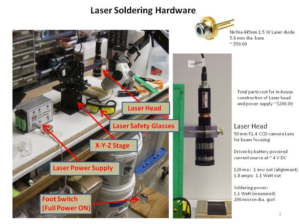
Safety was a major part of the design. The three 18650 batteries that power the laser are mounted on the outside of the case to make it easy to render the laser safe by removing the batteries when the device is not in use and making it easy to verify at a glance that the batteries are not in place.
In addition to the front panel indicator lights, there are also audible tones that indicate when the laser is on at either the low power (1 mw) aiming mode or at the high power (1.1 watt) soldering mode.
The materials on the printed circuit boards used, including the tinned solder pads, had enough fluorescent response to 445nm laser light that the 1mw aiming spot was easily visible even with (the absolutely required) laser safety glasses on.
The 50 mm F1.4 CCD camera lens was used in order to project a clean, small spot at a stand-off distance sufficient to perform the soldering operation by hand, viewable at a distance by a binocular inspection microscope. The rapidly defocused geometry of the beam past the focal spot adds an additional safety factor. There was a significant power penalty though compared with using the low F ratio aspheric lenses purposely designed for constructing high power efficiency "burning lasers."
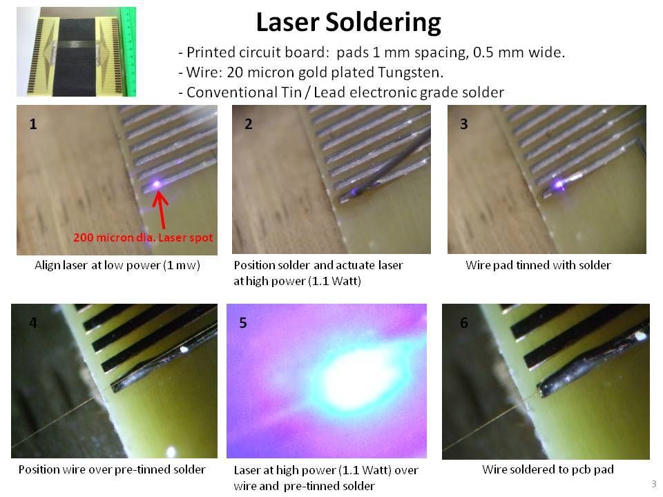
Here is the soldering sequence that was used.
Some observations:
Successful soldering was highly dependent upon the position of the spot on the solder to be melted. Sometimes, shifting the spot position on a tinned pad by just a few tens of microns made the difference between a fast re-melt with a cleanly soldered wire and having the solder stay solid under the same laser illumination.
Laser soldering wires to large surface area pads was unsuccessful. The most probable reason was that the large area copper strips conducted away the small amounts of heat that the laser delivered at a high enough rate that the temperature stayed below that needed to melt the solder.
If anyone were to build a rig similar to this for laser soldering, the use of a higher power diode than what is in this prototype device is strongly recommended.


