- Joined
- Aug 19, 2013
- Messages
- 82
- Points
- 8
then id like to participate. 
I was working on this anyway.
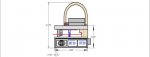
8 gram co2, no2 cooled.
spring touch focus.
650nm protective front sight window, for fun goggles still very necessary.
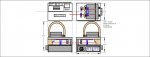
all in a 6061 bare aluminum host with stainless fittings. and sealed wiring.
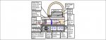
I have found a battery listed below
I have decided on three parallel 1.8amp drivers for 5.4a
anyway...
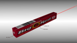
the luzy
http://laserpointerforums.com/f50/c-mount-luzy-laser-pistol-85484.html


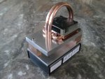
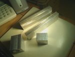
finally got the lens, the lens guide tube, and the heat sink rod.
Ordered the drivers tonight.
Also found a perfect battery, Sony camera 7.2v 4800mah NP-FV100 It is just about exact dimensions of the inside of the box. A way better choice than the 2 parallel 9v's with 1000mah.
This contest has defiantly succeeded in its stated goal of getting people like me out of the woodwork.
I was working on this anyway.
8 gram co2, no2 cooled.
spring touch focus.
650nm protective front sight window, for fun goggles still very necessary.
all in a 6061 bare aluminum host with stainless fittings. and sealed wiring.
I have found a battery listed below
I have decided on three parallel 1.8amp drivers for 5.4a
anyway...
the luzy
http://laserpointerforums.com/f50/c-mount-luzy-laser-pistol-85484.html
finally got the lens, the lens guide tube, and the heat sink rod.
Ordered the drivers tonight.
Also found a perfect battery, Sony camera 7.2v 4800mah NP-FV100 It is just about exact dimensions of the inside of the box. A way better choice than the 2 parallel 9v's with 1000mah.
This contest has defiantly succeeded in its stated goal of getting people like me out of the woodwork.
Last edited: