

How I Built My First Laser
Building you own laser is a rewarding experience. Not only is there a coolness to seeing what you built, but there's the ability to chose and set your own design parameters to your own build.
If you have built other electronics projects, you'll find that building your own isn't that hard to do. If you are good at soldering and have a basic understanding of electronics, odds are very good that you will be successful at it.
As tempting as it was to start out with a 1.6 watt blue laser, I decided to start out simple with a much lower power level, only 100mW (0.1 watts). I chose Green for the color because the bean is so bright and visible.
Getting the laser diode is easy, DTR's Laser Shop had exactly what I needed. The 3.8mm 50mW 520nm green laser diode was well documented telling me what I needed to know about supply current, voltage drop, and power output. While everything varies, at least I had a good idea what to expect. I chose the 520nm Osram PL520 Diode In Copper Module W/Leads & 405-G-2 Lens for $88 (USA).
https://sites.google.com/site/dtrlpf/home/diodes/pl520-520nm-laser-diode
If I wanted to save money and get a bit more power, I could have gone with the 450nm Osram PL450B Diode In Copper Module W/Leads & Three Element Glass Lens $47 (USA)
https://sites.google.com/site/dtrlpf/home/diodes/450nm-pl450-diodes
While tempting, the Green just looks so great, I went with Green for the brightness.
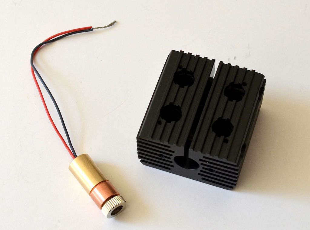
The Heat Sink came from Z-Bolt, "Heat Sink for 12 mm Modules" $20 (USA). After I ordered the heat sink, I did spot it for a few dollars less on another shop, but now I can't find the link to it.
Heat Sink for 12 mm Modules
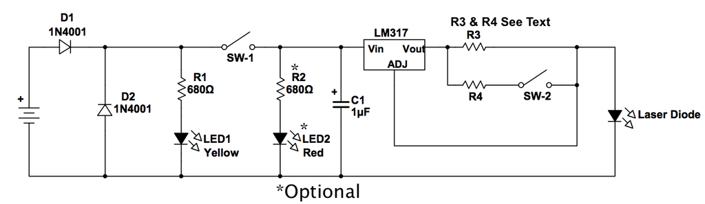
The design that I used is a modification to a design I saw here on the Laser Pointer Forum. Both D1 and D2 were added just in case I went brain dead and plugged the battery or AC supply in backward. D1 prevents the reverse flow of current and D2 takes the voltage off the other components.
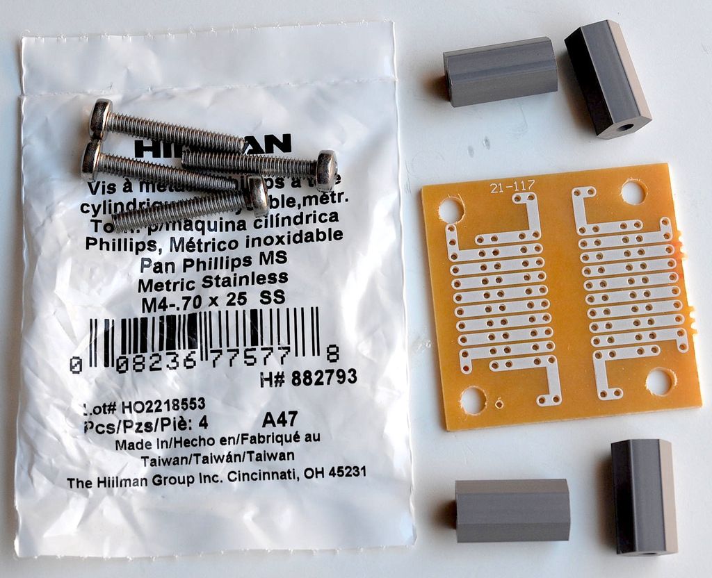
The Datac Prototyping Board # 12-607 turned out to be the ideal size to match the Heat-sink. I did have to enlarge the holes so that the M4-.70x25 metric screws would fit properly. The nylon spacers also had to be opened up a bit too.
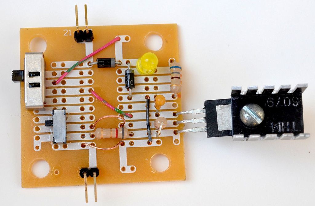
The V+ connection is at the top of the image and the V- or ground connection is at the bottom of the image. Any voltage from 12 volts to 15 volts works OK and it might even work down to about 10 volts. The On/Off Switch is the larger switch and the High/Low Power Selection Switch is the smaller switch. Things were getting a bit tight, so I skipped putting in R2 and LED2. Because I wanted to run all sorts of tests on the finished board, I did leave some copper loops that I could attach clip leads to for measurements.
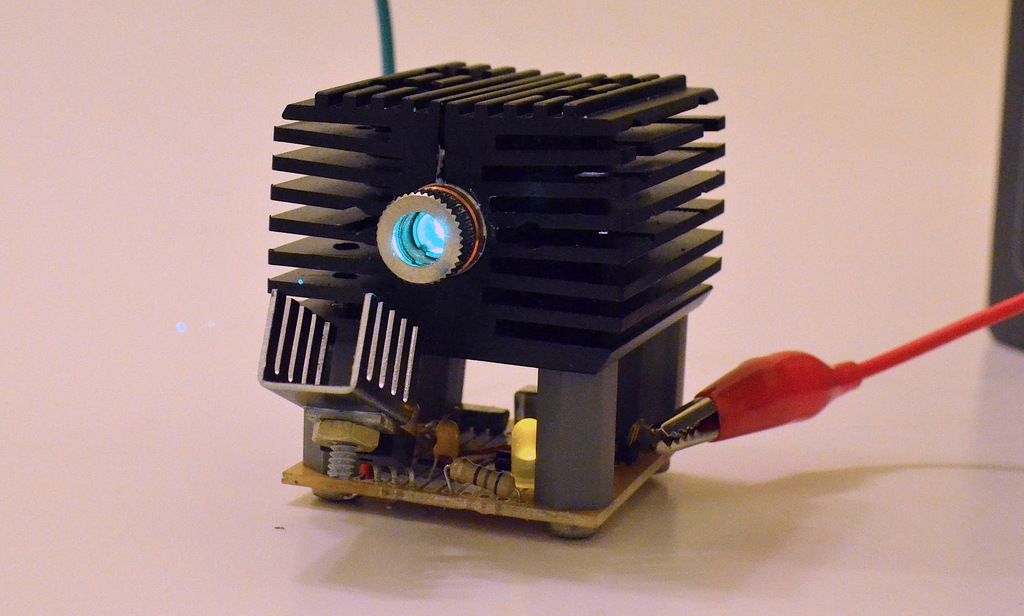
I knew the voltage regulator would be in the way, so I bent it down in front outside of the circuit. In high power mode at 300mA, the hottest thing is the voltage regulator. I measured it at 115 degrees F (46 C) after running for 5 minutes. The heat-sink for the laser measures 89 degrees F (32 C) after 5 minutes. I have yet to test how hot the voltage regulator would be if I leave off the heat sink.

As far as performance I was amazed at how well it did. In low power mode, roughly 55mW, I could light a match and pop black balloons. In full power mode the balloons pop faster and the match lights quicker. Both videos were shot in full power mode.
https://www.youtube.com/watch?v=ZRrG2y5DHEk
https://www.youtube.com/watch?v=lzR-5Mx6XbY
Selecting R3 & R4 Resistors:
A conservative choice would be both set at 12Ω. That would result in a High/Low current of 104mA and 208mA (28mW and 80mW power). Remember all power levels are my best guess based on DTR's Data.
A more liberal approach would use 10Ω resistors for R3 & R4. That would result in a High/Low current of 125mA and 250mA (42mW and 96mW power). This is 50mA higher that the specification for the diode, so the life may be a bit shorter.
A radical approach would be to use 8.2Ω resistors for R3 & R4. That would result in a High/Low current of 152mA and 305mA (55mW and 108mW power). Clearly well beyond the specification and it will shorten the life of the diode, but no one knows by how much.
I started with 8.2Ω resistors, but after testing it for a while, I'm going to switch it so that R4 = 13Ω. That would result in a High/Low current of 152mA and 250mA (55mW and 96mW power). Because the laser burned so well even in low power mode, I decided not to risk making the life too short. It is after all, my first home brew laser and it's a bit like my first love.
Other Things:
C1 is a 1uF Tantalum Capacitor. Like other Tantalum Capacitors is has a polarity, watch out for the + and -. The + lead is longer than the - lead. If you wire the capacitor backward Tantalum Capacitors have been known to explode, so be careful. If you want, you could use a 0.1uF Ceramic Capacitor. The Ceramic Capacitors operate either way and don't explode if put in backward.
The resistors can be either 1/2 watt or 1/4 watt, whatever you like to use.
If you haven't guessed it yet, SW-1 is the On/Off Switch and SW-2 is the High/Low Power Switch.
R1 & R2 and their matching LED1 & LED2 aren't really required for the circuit to work. They are just power indicators. LED1 indicated that power is connected and LED2 shows that power is connected AND the laser is turned on.
What's Next:
I did spot a 3.8mm 300mW 650nm Single Mode Diodes on DTR's Shop. It's only $21 with Copper Module, Leads & Acrylic Lens. It's really tempting to try and see if I could build this really cheap. All Electronics does sell some low cost heat sinks that I might be able to modify... but I may have to wait a bit before my next build. My wife put up with this one, but if I do too much too quickly it's not the laser that will get too hot on me. :beer:
In closing I do want to say that DTR's Shop ROCKS !!! He was VERY helpful and was very prompt in answering my questions. I will be purchasing from him again . . . after my wife calms down.") I give him 5 out of 5 stars!!!
I give him 5 out of 5 stars!!!
Bob Diaz
Building you own laser is a rewarding experience. Not only is there a coolness to seeing what you built, but there's the ability to chose and set your own design parameters to your own build.
If you have built other electronics projects, you'll find that building your own isn't that hard to do. If you are good at soldering and have a basic understanding of electronics, odds are very good that you will be successful at it.
As tempting as it was to start out with a 1.6 watt blue laser, I decided to start out simple with a much lower power level, only 100mW (0.1 watts). I chose Green for the color because the bean is so bright and visible.
Getting the laser diode is easy, DTR's Laser Shop had exactly what I needed. The 3.8mm 50mW 520nm green laser diode was well documented telling me what I needed to know about supply current, voltage drop, and power output. While everything varies, at least I had a good idea what to expect. I chose the 520nm Osram PL520 Diode In Copper Module W/Leads & 405-G-2 Lens for $88 (USA).
https://sites.google.com/site/dtrlpf/home/diodes/pl520-520nm-laser-diode
If I wanted to save money and get a bit more power, I could have gone with the 450nm Osram PL450B Diode In Copper Module W/Leads & Three Element Glass Lens $47 (USA)
https://sites.google.com/site/dtrlpf/home/diodes/450nm-pl450-diodes
While tempting, the Green just looks so great, I went with Green for the brightness.

The Heat Sink came from Z-Bolt, "Heat Sink for 12 mm Modules" $20 (USA). After I ordered the heat sink, I did spot it for a few dollars less on another shop, but now I can't find the link to it.
Heat Sink for 12 mm Modules

The design that I used is a modification to a design I saw here on the Laser Pointer Forum. Both D1 and D2 were added just in case I went brain dead and plugged the battery or AC supply in backward. D1 prevents the reverse flow of current and D2 takes the voltage off the other components.

The Datac Prototyping Board # 12-607 turned out to be the ideal size to match the Heat-sink. I did have to enlarge the holes so that the M4-.70x25 metric screws would fit properly. The nylon spacers also had to be opened up a bit too.

The V+ connection is at the top of the image and the V- or ground connection is at the bottom of the image. Any voltage from 12 volts to 15 volts works OK and it might even work down to about 10 volts. The On/Off Switch is the larger switch and the High/Low Power Selection Switch is the smaller switch. Things were getting a bit tight, so I skipped putting in R2 and LED2. Because I wanted to run all sorts of tests on the finished board, I did leave some copper loops that I could attach clip leads to for measurements.

I knew the voltage regulator would be in the way, so I bent it down in front outside of the circuit. In high power mode at 300mA, the hottest thing is the voltage regulator. I measured it at 115 degrees F (46 C) after running for 5 minutes. The heat-sink for the laser measures 89 degrees F (32 C) after 5 minutes. I have yet to test how hot the voltage regulator would be if I leave off the heat sink.

As far as performance I was amazed at how well it did. In low power mode, roughly 55mW, I could light a match and pop black balloons. In full power mode the balloons pop faster and the match lights quicker. Both videos were shot in full power mode.
https://www.youtube.com/watch?v=ZRrG2y5DHEk
https://www.youtube.com/watch?v=lzR-5Mx6XbY
Selecting R3 & R4 Resistors:
A conservative choice would be both set at 12Ω. That would result in a High/Low current of 104mA and 208mA (28mW and 80mW power). Remember all power levels are my best guess based on DTR's Data.
A more liberal approach would use 10Ω resistors for R3 & R4. That would result in a High/Low current of 125mA and 250mA (42mW and 96mW power). This is 50mA higher that the specification for the diode, so the life may be a bit shorter.
A radical approach would be to use 8.2Ω resistors for R3 & R4. That would result in a High/Low current of 152mA and 305mA (55mW and 108mW power). Clearly well beyond the specification and it will shorten the life of the diode, but no one knows by how much.
I started with 8.2Ω resistors, but after testing it for a while, I'm going to switch it so that R4 = 13Ω. That would result in a High/Low current of 152mA and 250mA (55mW and 96mW power). Because the laser burned so well even in low power mode, I decided not to risk making the life too short. It is after all, my first home brew laser and it's a bit like my first love.
Other Things:
C1 is a 1uF Tantalum Capacitor. Like other Tantalum Capacitors is has a polarity, watch out for the + and -. The + lead is longer than the - lead. If you wire the capacitor backward Tantalum Capacitors have been known to explode, so be careful. If you want, you could use a 0.1uF Ceramic Capacitor. The Ceramic Capacitors operate either way and don't explode if put in backward.
The resistors can be either 1/2 watt or 1/4 watt, whatever you like to use.
If you haven't guessed it yet, SW-1 is the On/Off Switch and SW-2 is the High/Low Power Switch.
R1 & R2 and their matching LED1 & LED2 aren't really required for the circuit to work. They are just power indicators. LED1 indicated that power is connected and LED2 shows that power is connected AND the laser is turned on.
What's Next:
I did spot a 3.8mm 300mW 650nm Single Mode Diodes on DTR's Shop. It's only $21 with Copper Module, Leads & Acrylic Lens. It's really tempting to try and see if I could build this really cheap. All Electronics does sell some low cost heat sinks that I might be able to modify... but I may have to wait a bit before my next build. My wife put up with this one, but if I do too much too quickly it's not the laser that will get too hot on me. :beer:
In closing I do want to say that DTR's Shop ROCKS !!! He was VERY helpful and was very prompt in answering my questions. I will be purchasing from him again . . . after my wife calms down.
I give him 5 out of 5 stars!!!Bob Diaz
Last edited:


")
.jpg)

