Welcome to Laser Pointer Forums - discuss green laser pointers, blue laser pointers, and all types of lasers

LPF Donation via Stripe | LPF Donation - Other Methods

Links below open in new window

ArcticMyst Security by Avery

Harvesting the ShowWX? Contains: 635 + 445 (single mode?) + 532 (directly doubled)

rhd

0
Joined
Dec 7, 2010
Messages
8,475
Points
0
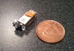
Do you seriously expect to fit all those 12mm modules in there?
Or do you think you can somehow build it outside the original case?

See \/

Hm, what about modding the insides and inserting the diodes right in place of the older ones? The 532 would be a problem tho.

The chances of me getting the 3.8mm out cleanly enough to have a moddable result for the 5.6s is pretty slim though.

Really, this part of the project is absurdly speculative until I see what this actually looks like. But I am going to keep it in mind when I do the teardown.

Regarding the 532 - If I thought there was a potential that I could create a working pico projector after replacing the blue and reds, I'd probably just leave the stock 532 inside. That's the least intriguing diode in this thing.


rhd

0
Joined
Dec 7, 2010
Messages
8,475
Points
0
Good news - this guy will probably be reaching my hands tomorrow :)
 

LaZeRz

0
Joined
Feb 19, 2011
Messages
2,549
Points
63
Dude, I cant wait to see whats gonna come out of this thing!

post some pics for us!

:D

a 532 diode would be pretty cool aswell
 
Last edited:

rhd

0
Joined
Dec 7, 2010
Messages
8,475
Points
0
I have to warn everyone - you're going to get harvest/disassembly pics long before you get test results and/or beam shots. My 3.8mm modules are not yet on their way to me. Shortly - this week, but they've still got to make the journey from the UK.

I'm also not going to post beam/power/wavelength info or photos until some diffraction gratings I ordered arrive. I want to be able to identify the wavelength (particularly of the blue).

So there are a couple roadblocks before you see output, but I'll probably harvest in the next few days, and get around to posting a harvest guide this weekend.

One other note - I'll probably do it in a new thread that removes the actual name of the manufacturer. I know this isn't quite the same as the KasEO hoopla, but just in case, I'd like to avoid any frustration for the board/forum/avery. I could edit the OP title, but it would still be in everyone who has replied's messages.
 
Last edited:

rhd

0
Joined
Dec 7, 2010
Messages
8,475
Points
0
Teaser:

attachment.php


Red and Blue diodes removed. Green laser left in. Putting serious though into getting this thing modified to use a cheap LOC and a typical 445. It's hard to explain the physical reason why - but essentially, I think it is very largely possible. The size of everything suggests that I can do this without much trouble - without (probably) physically modifying the assembly at all.

Since I don't have my 3.8mm modules yet, I've spent the past 2 hours trying to trick the circuitry into powering up without the red/blue diodes. I've got it going with a combination of IN4001 diodes to trick the circuitry, but it's clear that they've got a system to check for faults. (I think two missing diodes would count).

As much as it is pretty cool to see the thing fire up all-green, it faults out in about 60 seconds. Though the menus are all operable in the mean time. To be fair, I'm not sure whether this is a diode-check triggering the fault, or just general heating of the IC chips since I'm running it outside of the heatsinking case.

I'm very comfortable saying that this IS the Opnext diode I thought it was here:
http://catalog.osram-os.com/jsp/dow...0.pdf&url=/media//_en/Graphics/00049856_0.pdf

I'm still not sure I know what the red is. It's an Opnext, but not sure on the specific model yet.

Oh and by the way... both diodes harvest successfully, and testing working ;)
 

Attachments

  • green.jpg
    green.jpg
    57.5 KB · Views: 754
Last edited:

DTR

0
Joined
Jun 24, 2010
Messages
5,684
Points
113
Nice. Glad to see it made it's way to you safe and sound.:beer:
 

rhd

0
Joined
Dec 7, 2010
Messages
8,475
Points
0
The smallest 60mW green I've ever seen. Has 4 pins though - and I'm stumped at how the pinout works :(

attachment.php
 

Attachments

  • green2.png
    green2.png
    552.9 KB · Views: 952
Last edited:

rhd

0
Joined
Dec 7, 2010
Messages
8,475
Points
0
Does anyone have any idea why there would be four pins going into this little gem?

It's the Corning G-1000 Green Laser. It's not exactly DPSS, but same concept. Inside that "box" is an IR 1064 diode, being directly doubled. I have no idea why there are four pins.

Using a DMM I determined that:

2 of the pins have continuity in both directions
2 of the pins (the OTHER two) have continuity in one direction
The 2 sets of 2 have NO continuity with each other
 
Last edited:

LaZeRz

0
Joined
Feb 19, 2011
Messages
2,549
Points
63
Try em all :eg: I've carelessy direct driven a LOC diode after fumbling with it for a few mins trying to find the pinout and it didnt die from reverse polarity, probably cause it was running kipkay style and it didnt have anything trying to pump the opposite polarities into it
 
Last edited:

rhd

0
Joined
Dec 7, 2010
Messages
8,475
Points
0
Tried that - no love. I'm inclined to think that the other pins actually need some sort of enable signal... though I can't figure out why. I suppose the other pins might be a photo diode.

That said, I just found this claim about the G-1000:
"provides a power-efficient solution with 8% wall-plug efficiency (WPE), and longer battery life;"

So, working backwards. 60mW output implies:
(100/8) x 60 = 750mW input

If we assume it to be a typical IR, then probably about 2.5V input. So roughly, the current in needs should be ~300mA.

It's a long shot of course, and a lot of presumptions are being made. But I tried the pair of two pins that had one-direction polarity as per my DMM, and I tried them at:

60mA (first), then: 80mA, 100mA, 125mA, 175mA, 200mA, 250mA and then stopped.

It is possible that this requires higher current to lase, but I'm not going to try that until it's really a last resort.
 

anselm

0
Joined
Nov 22, 2010
Messages
2,448
Points
0
Nice job so far.
The extra two pins might be feedback and modulation.....

From my experience, you want to find a pair of pins that is continuous in one direction
and blocks in the other, while probing with the DMM diode test, not hundreds of mA.
Those two pins will likely be anode and cathode.
 
Last edited:

rhd

0
Joined
Dec 7, 2010
Messages
8,475
Points
0
Ya - I've found the one-directional continuity pins, but no luck powering them. This has left me wondering whether some sort of modulation is required to enable this guy.


Top