- Joined
- Jan 14, 2011
- Messages
- 3,816
- Points
- 63
Hey all.
So for the last month or two I have been planning, thinking about, and building my DIY LPM from this circuit: http://laserpointerforums.com/f42/diy-thermal-lpm-under-50-a-51129.html.
I finally finished it yesterday. There are still a couple of kinks (depending on how the plug is situated, something shorts or something and causes it to measure directly the voltage that's incoming? I dunno. Anyway, it usually works.), but other than that, it works perfectly.
So here are some pictures of it.

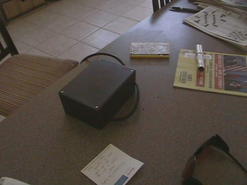
The back.

The TEC.

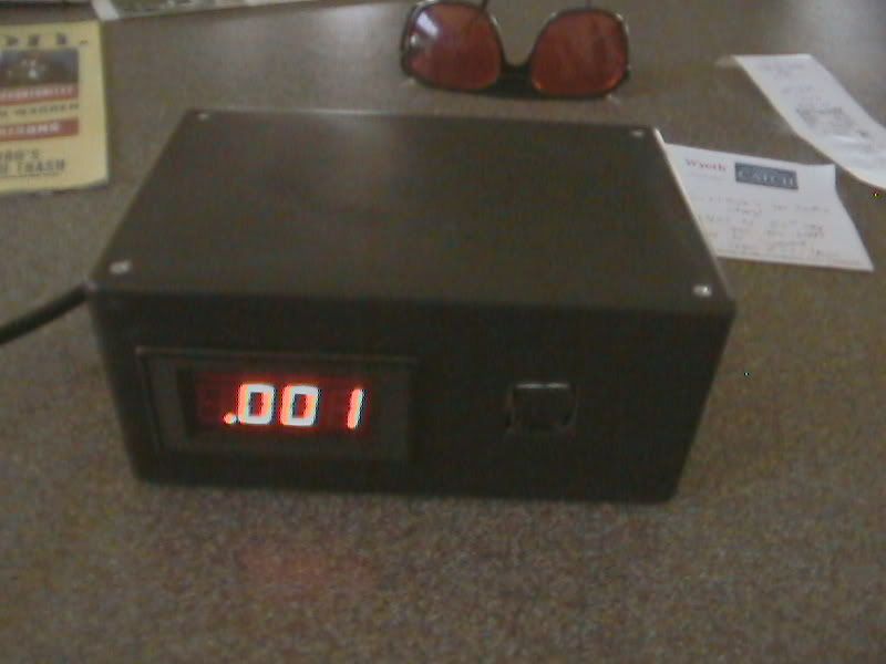
The front, in all its professional looking glory (or at least I think so).
And here's a video.
YouTube - DIY Laser Power Meter
I apologize for when my mom asks me who I am talking to... she's a bit paranoid that way. Nonetheless, it's a decent video, no?
Anyway, so I promised I would explain it.
So first, I made the circuit described in the thread above by using some copper clad, some toner, and some cupric chloride as my etchant. I put down the components (was not very easy with those trimmers), and plugged in some wires.
The box I used in this build was a RadioShack project box, and it fits nicely and looks good. Used a jigsaw to cut out the holes for the panel and the TEC module.
The hard part was getting a power supply to it. I ended up attaching a 3-pin (including GND) male socket to the input of a 2-pin AC Adapter, outputting 320mA and 5.3VDC. I attached the GND of the 3-pin socket to the GND of the circuit so that the GNDs were isolated and the panel could read correctly. That was the biggest catch in this design.
Anyway, it was a fun build and I hope ya'll like it!
So for the last month or two I have been planning, thinking about, and building my DIY LPM from this circuit: http://laserpointerforums.com/f42/diy-thermal-lpm-under-50-a-51129.html.
I finally finished it yesterday. There are still a couple of kinks (depending on how the plug is situated, something shorts or something and causes it to measure directly the voltage that's incoming? I dunno. Anyway, it usually works.), but other than that, it works perfectly.
So here are some pictures of it.

The back.

The TEC.

The front, in all its professional looking glory (or at least I think so).
And here's a video.
YouTube - DIY Laser Power Meter
I apologize for when my mom asks me who I am talking to... she's a bit paranoid that way. Nonetheless, it's a decent video, no?
Anyway, so I promised I would explain it.
So first, I made the circuit described in the thread above by using some copper clad, some toner, and some cupric chloride as my etchant. I put down the components (was not very easy with those trimmers), and plugged in some wires.
The box I used in this build was a RadioShack project box, and it fits nicely and looks good. Used a jigsaw to cut out the holes for the panel and the TEC module.
The hard part was getting a power supply to it. I ended up attaching a 3-pin (including GND) male socket to the input of a 2-pin AC Adapter, outputting 320mA and 5.3VDC. I attached the GND of the 3-pin socket to the GND of the circuit so that the GNDs were isolated and the panel could read correctly. That was the biggest catch in this design.
Anyway, it was a fun build and I hope ya'll like it!


