

so the title says it all... 
basically i ran into this site when i was constructing stuff for my thesis (my thesis for a masterals course in medical technology, about the farthest course from light related physics and electronics and high voltage work LOL)
and i do believe a certain Youtube personality who goes by the name of "tingawinga5" also pointed this way with regards to the diode driver circuit.
so a little introduction to my little prototype for a bigger prototype just to show my nitpicking thesis advisers that a high powered laser can be built using cheap materials.
the circuit is based off of the LM 317T regulator, with a pair of 1-ohm 1/2 watt resistors and a 10uF 16V capacitor, and a pair of 1N4001 diodes. it runs normally on a 6V power source, but since my battery clip is a 9V clip, it may also run on 9 volts.
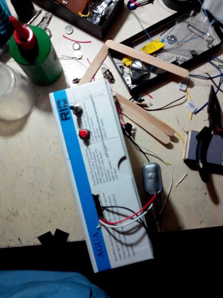
the regulator is heatsinked, as is the diode, secured to the sink with a CD-ROM laser mount (which i disassembled and to my dismay didn't quite go as planned)
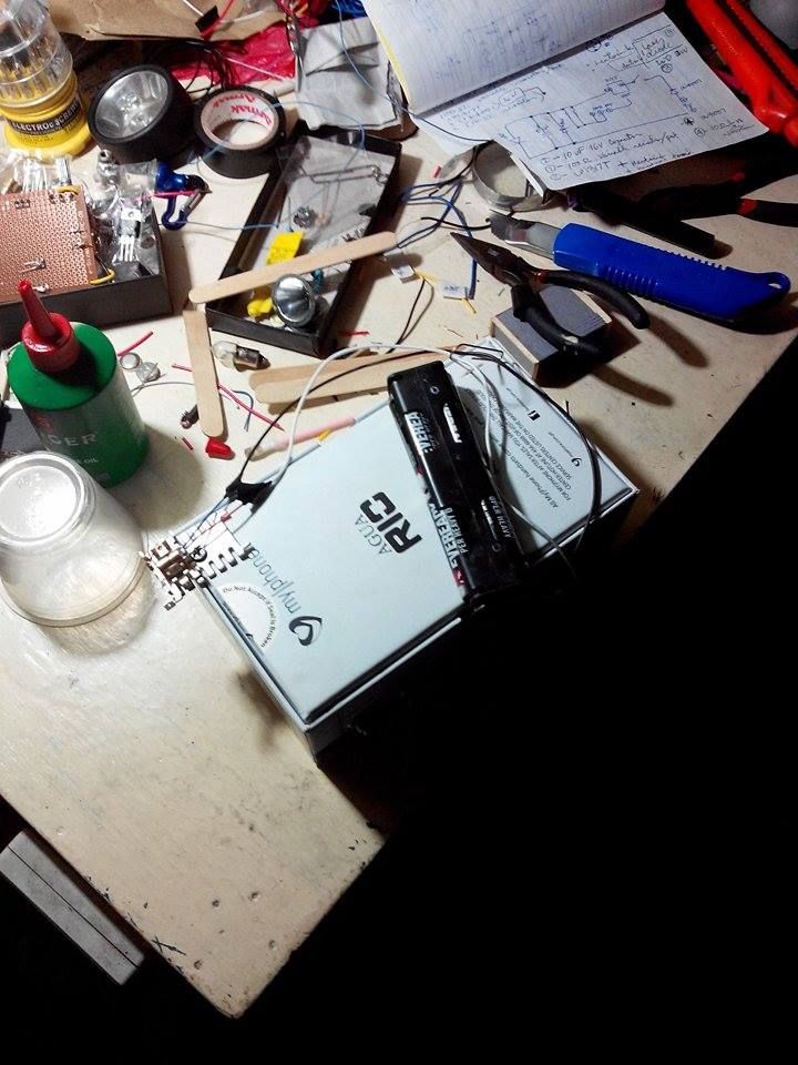
circuit box stuffed inside a mobile phone's box, with two screw-clamp 2-terminal blocks as the leads for the diode and the power source. which means i can hook the circuit box to anything - ANYTHING - that has power and has 2 wires.
also very handy since in my country, the philippines, power cuts are often the norm and i also tested the box on "brite white" 3W LED lamps which produced a blinding warm glow.
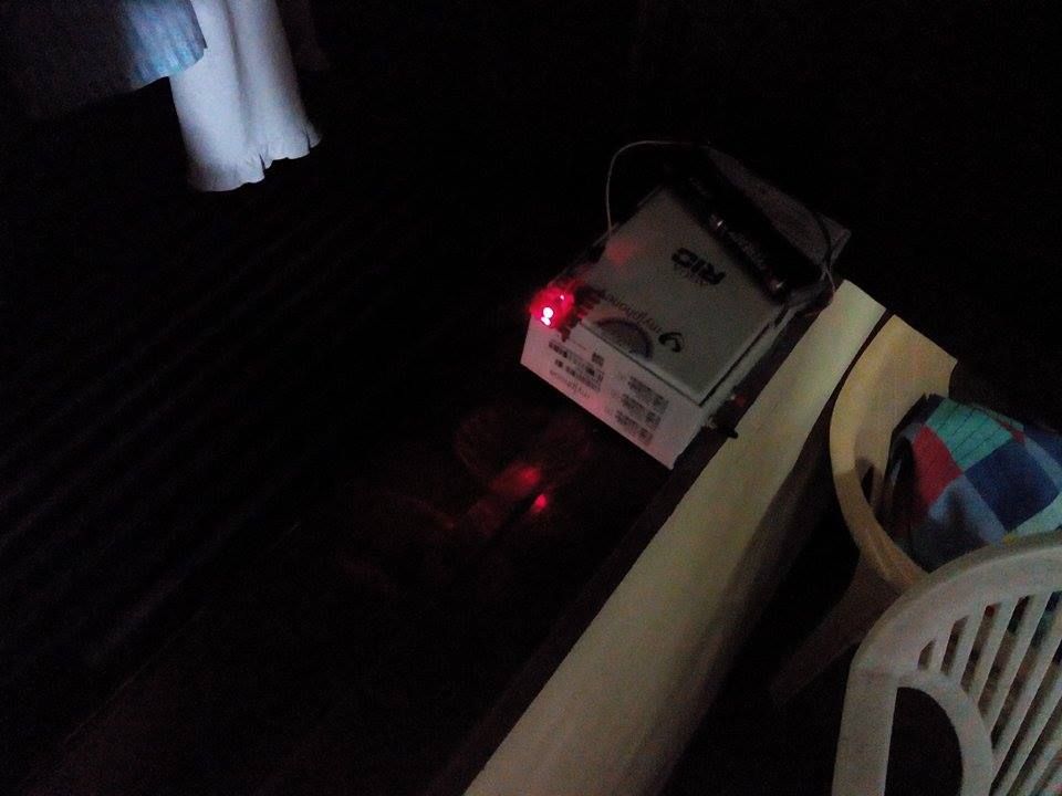
the diode is a cheap red laser pointer replacement set with the heavy copper housing built in. this means i can't really adjust the beam's focus because if i wanted to do that i might fart up the diode - besides, this is a prototype, i'll be using the same box to drive a better and more powerful lamp with a wavelength of about 450nm, perhaps targeting the 5-watt output range because of the nature of the thesis proposal.
dear me, i'm getting all chatty again. anyway, here are a couple of pictures. forgive my table, it's rather messy.
PS i purposely omitted the 100-ohm variable resistor because every single electronics shop here has 500 ohms as the lowest - and one of the salesladies even INSISTED i was wrong, much to my amusement.
PPS i also installed a "capacitor discharger safety button" so i can press it and be absolutely sure i am not frying a new diode when installing. it's the red button beside the main toggle switch. it's wired to both leads of my capacitor, and is a "push to close" type of switch.
basically i ran into this site when i was constructing stuff for my thesis (my thesis for a masterals course in medical technology, about the farthest course from light related physics and electronics and high voltage work LOL)
and i do believe a certain Youtube personality who goes by the name of "tingawinga5" also pointed this way with regards to the diode driver circuit.
so a little introduction to my little prototype for a bigger prototype just to show my nitpicking thesis advisers that a high powered laser can be built using cheap materials.
the circuit is based off of the LM 317T regulator, with a pair of 1-ohm 1/2 watt resistors and a 10uF 16V capacitor, and a pair of 1N4001 diodes. it runs normally on a 6V power source, but since my battery clip is a 9V clip, it may also run on 9 volts.
the regulator is heatsinked, as is the diode, secured to the sink with a CD-ROM laser mount (which i disassembled and to my dismay didn't quite go as planned)
circuit box stuffed inside a mobile phone's box, with two screw-clamp 2-terminal blocks as the leads for the diode and the power source. which means i can hook the circuit box to anything - ANYTHING - that has power and has 2 wires.
also very handy since in my country, the philippines, power cuts are often the norm and i also tested the box on "brite white" 3W LED lamps which produced a blinding warm glow.
the diode is a cheap red laser pointer replacement set with the heavy copper housing built in. this means i can't really adjust the beam's focus because if i wanted to do that i might fart up the diode - besides, this is a prototype, i'll be using the same box to drive a better and more powerful lamp with a wavelength of about 450nm, perhaps targeting the 5-watt output range because of the nature of the thesis proposal.
dear me, i'm getting all chatty again. anyway, here are a couple of pictures. forgive my table, it's rather messy.
PS i purposely omitted the 100-ohm variable resistor because every single electronics shop here has 500 ohms as the lowest - and one of the salesladies even INSISTED i was wrong, much to my amusement.
PPS i also installed a "capacitor discharger safety button" so i can press it and be absolutely sure i am not frying a new diode when installing. it's the red button beside the main toggle switch. it's wired to both leads of my capacitor, and is a "push to close" type of switch.


