Welcome to Laser Pointer Forums - discuss green laser pointers, blue laser pointers, and all types of lasers

LPF Donation via Stripe | LPF Donation - Other Methods

Links below open in new window

ArcticMyst Security by Avery

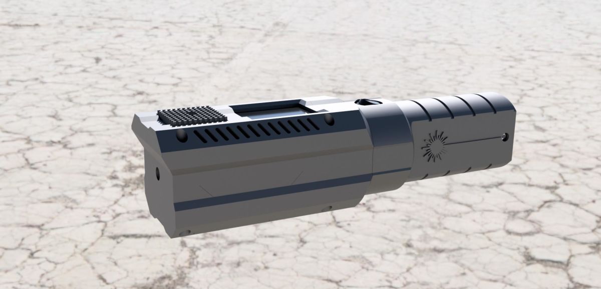
Arctic's Open Source RGB Laser Host


Joined
Apr 6, 2014
Messages
2,436
Points
113
With 4duino it would be actually quite easy add digital controls for RGB laser.

Yes, exactly, I was actually thinking of adding an Arduino digital control for my micro RGB build, you can even control it from your iPhone via Bluetooth or wifi.
But after diachi's suggestion of just using adjustable slider Pots for analogue control, that's the way I went and had some nice RGB coloured buttons printed for my three sliders as well.
Also note that I think diachi said you get better control via analogue control over the Arduino which uses PWM

:)
 
Last edited:
Joined
Jun 22, 2016
Messages
2,686
Points
113
ArticDude--that 4duino 24 is a reasonably priced add on-nice find--only $79 4D Systems | 4Duino-24

You should check out PyBoard too!!

PyBoard Store >>

LCD skin for PyBoard >>

Nice features of this hardware:

3x 12-bit analog to digital converters, 2x 12-bit digital to analog (DAC) converters, On-board 3.3V LDO voltage regulator, capable of supplying up to 250mA, input voltage range 3.6V to 16V

..But,
logic level converters would be also needed with PyBoard for this project, since it logic runs 3.3V.
 
Joined
Jan 30, 2017
Messages
5
Points
3
Looks awesome. I'm in the process of printing it right now. Didn't realize how massive this thing is.

Couple questions:

Where did you get the 20mm battery contacts?

and

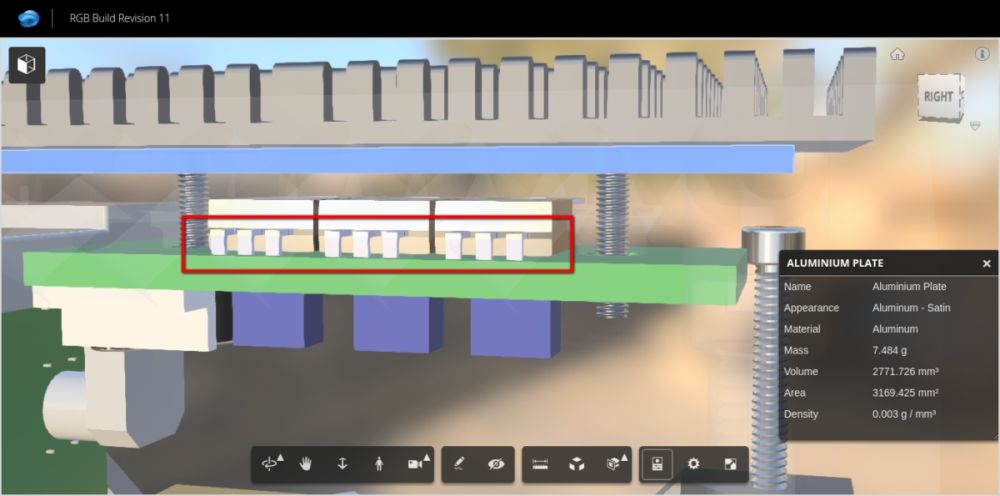
Do the heat-sinks sit against the FETs on the driver board? it looks like there's a gap between them
 
Joined
Jun 22, 2016
Messages
2,686
Points
113
Which material you are printing?

Yes, there is gap between FET's and Al plate beacuse, On mine OptLasers driver board Mosfet legs were inserted quite deep before soldering so they couldnt bend to full 90 degree angle.

driverboard_gap_eenl6q.jpg


I used Phobya 3mm Thermal Pad Ultra 5W/mk to fill gap >>

20mm contact board:
20mm Partition Board / Contact PCB
 
Joined
Jan 30, 2017
Messages
5
Points
3
I'm using some spare PLA I have to see how it looks, I really like that translucent look so i might consider getting some PETG
 
Joined
Jun 22, 2016
Messages
2,686
Points
113
I'm using some spare PLA I have to see how it looks, I really like that translucent look so i might consider getting some PETG

Can you post your results here?! What filament & printer was used. And secondly would all the parts fit together?

-I have thoughts that PLA may shrink too much and parts ain't fit together without sanding etc. 3D files tolerances are +/- 0,2mm

Thanks! :thanks:
 
Joined
Jan 30, 2017
Messages
5
Points
3
Can you post your results here?! What filament & printer was used. And secondly would all the parts fit together?

-I have thoughts that PLA may shrink too much and parts ain't fit together without sanding etc. 3D files tolerances are +/- 0,2mm

Thanks! :thanks:

Sure! I sill have the mid section to print.

I'm using hatchbox black pla on an upgraded printrbot simple metal.

I had a couple minutes of sanding and had to drill out all of the mounting holes to get everything to fit, but it worked.

print album
 
Last edited:
Joined
Jun 22, 2016
Messages
2,686
Points
113
Sure! I sill have the mid section to print.

I'm using hatchbox black pla on an upgraded printrbot simple metal.

I had a couple minutes of sanding and had to drill out all of the mounting holes to get everything to fit, but it worked.

Ok. That is very good to know! Thank you for your input! :)

I was worrying that PET would shrink too much for fitting together.
 
Joined
Jun 22, 2016
Messages
2,686
Points
113
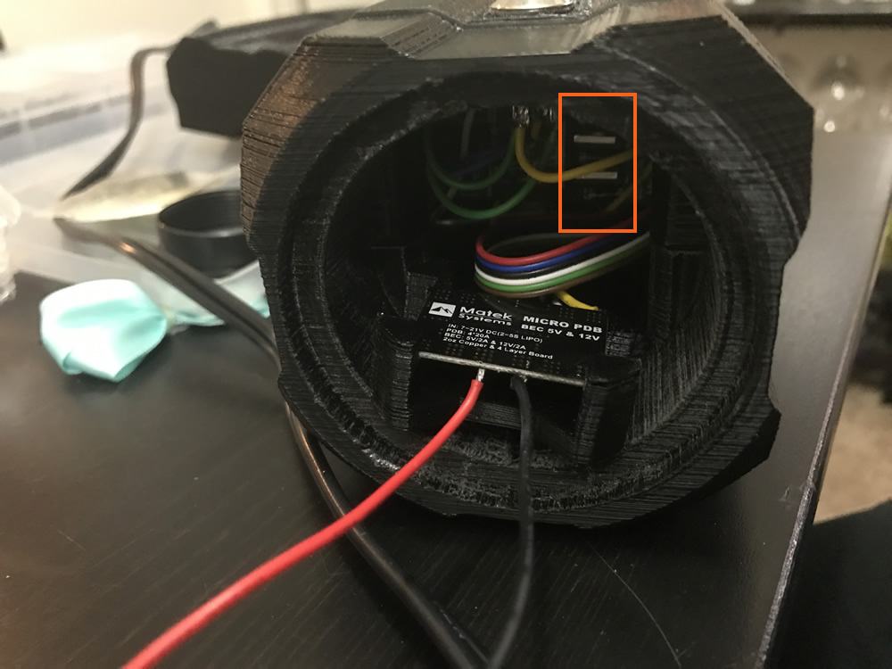
BTW you could leave RGB controller without those mosfets. We are olnly using PIC's logic, there is no "main load" for switching for RGB driver. PIC's logic voltage 5V is enough.

Umi6ajC_edit.jpg


Looks like same issue with your driver Mosfets that they would not bend full 90 degree.

dF0uhNZg.jpg


FpBRB3bg.jpg
 
Last edited:
Joined
Jan 30, 2017
Messages
5
Points
3
I did some upgrades/maintenance to my printer and reprinted every part. Finished the build and it looks amazing. Too the laser to the beach but couldn't take any pictures (camera isn't good enough).

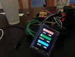
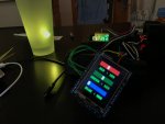
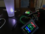
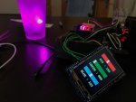
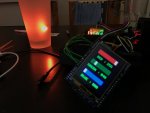
I like the idea of "digital input" some of you were talking about. I went ahead and bought a 4duino and have been messing around with it this afternoon.

I don't have the most experience with coding, but I currently have sliders to control the rgb channels individually. The color selection is amazing with this. I'll get some pictures up later
 
Joined
Jun 22, 2016
Messages
2,686
Points
113
I did some upgrades/maintenance to my printer and reprinted every part. Finished the build and it looks amazing. Too the laser to the beach but couldn't take any pictures (camera isn't good enough).

I like the idea of "digital input" some of you were talking about. I went ahead and bought a 4duino and have been messing around with it this afternoon.

I don't have the most experience with coding, but I currently have sliders to control the rgb channels individually. The color selection is amazing with this. I'll get some pictures up later

Sounds cool! :yh:

I could design new Top Frame for the host and 4duino. I think I saw 3D CAD file for 4duino on the site.
 
Joined
Jun 22, 2016
Messages
2,686
Points
113
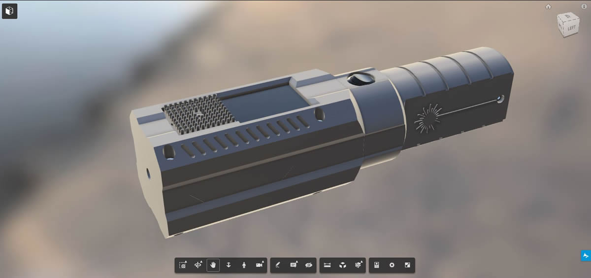
Top Frame for 4Duino


3D View >>


I will upload .STL file in few hours...

:beer:

---------

EDIT

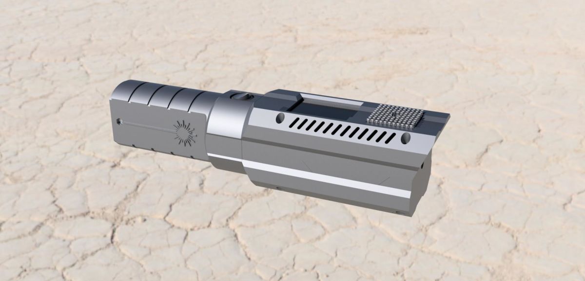
I noticed that OptLaser driver board did not fit with 4Duino so I had to add some "extra space" for TopFrame.

RGB_Build_Revision_11_B.jpg


RGB_Build_Revision_11_C.jpg


So here is two different versions of TopFrame for 4Duino:

TopFrame for 4Duino - REV11B & REV11C Download >>

Hopefully you are able to fit 4Duino in those. There's not too much of free space inside the host. :thinking:


I really hope to see some pictures of your RGB

:thanks:
 
Last edited:
Joined
Jan 30, 2017
Messages
5
Points
3
Beautiful colors. If you know what you are doing then the 4duino is perfect for custom color picking and effects!

I feel like Big Clive's programming is spectacular, but a little lacking. I didn't notice very much yellow and almost never saw orange.

My goal is to get a color picker on there instead of RGB sliders. Also want to be able to switch between color picker and a list of effects.

File_000.jpg
File_001.jpg
File_002.jpg
File_003.jpg
File_004.jpg
 
Joined
Jun 22, 2016
Messages
2,686
Points
113
Beautiful colors. If you know what you are doing then the 4duino is perfect for custom color picking and effects!

I feel like Big Clive's programming is spectacular, but a little lacking. I didn't notice very much yellow and almost never saw orange.

My goal is to get a color picker on there instead of RGB sliders. Also want to be able to switch between color picker and a list of effects.

What version of chip you got?
(Blue, Green or Red channel glows dimly for one second at power-up.)

Have you tried the "Colour touch" mode?

When I'm cycling colors with Option button on "Colour touch" I'm getting lots of orange and yellow.. :thinking:


I probably choosen 4Duino at a first place if I lived 2000km southern. Temperatures here on winter are usually below -25*C and touch screen is useless over here in winter time.

I'm probably going to make 4Duino 24 version for summer use.
 

Radim

0
Joined
Aug 17, 2016
Messages
1,458
Points
83
Awesome guys, that seems really nice. If I'll go for my own build once, this would be perfect. (Maybe I would add some connector for controlling it via phone as well - larger display for color selection in color space.) Unfortunatelly I cannot rep you again yet, ArcticDude, spreading time. So rep+ for Scout at least. ;)


Top