- Joined
- Feb 28, 2011
- Messages
- 66
- Points
- 0
I'm pretty sure this is the right section to be posting this...
I've been meaning to build a TEA nitrogen laser for a while now, only just got round to it.
My setup:
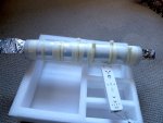
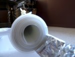
I have a 2mm thick piece of glass thats roughly 35cm by 25cm from an old scanner seperating 2 pieces of alaminium foil aprox 30cm by 20cm on either side. The glass is placed hoizontaly with the lower piece of foil being used as the ground. The upper sheet of alaminium foil is split into 2 about 2/3rds of the way along its length. I originally split it 50/50 but after seeing other designs I decided on the current configuration. I used the smaller top side for the HV in with sparkgap to ground, this is linked to the other side with 3 4.7Mohm resistors in series (using 1 or 2 just resulted in them arcing over). There is a 5mm gap between the 2 upper sheets of foil, between this gap are the laser electrodes. I tried many different electrodes but so far haven't had any luck. I'm currently using blanking plates from a computer case. Entire lasing channel is roughly 10cm long.
Power supply:
I'm using my homemade CO2 laser power supply with a handful of 4M7 resistors in series to limit the current. The power supply consists basically of a ZVS (push-pull) driver and a half-wave recitifed TV flyback transformer. It outputs aproximatly 20kV when used like this.
My problem:
I can't for the life of me get the laser to give any output, all I see is one or 2 sparks between the laser electrodes at fairly consistant places each time the sparkgap fires. I have tried moving and altering the electrodes many times, so far the most I have achived is about 10 to 15 sparks between the electrodes firing consistantly. From what I understand I should be getting a very even plasma discharge between the electrodes down their entire length.
Does anybody have any ideas on how I can achive an even plasma discharge?
From what I understand about these lasers these concentrated sparks are a result of the gas pressure being too high but I don't understand how atmopsheric pressure can be too high for an atmospheric pressure laser...
Oh and heres a video < Click the text
I've been meaning to build a TEA nitrogen laser for a while now, only just got round to it.
My setup:
I have a 2mm thick piece of glass thats roughly 35cm by 25cm from an old scanner seperating 2 pieces of alaminium foil aprox 30cm by 20cm on either side. The glass is placed hoizontaly with the lower piece of foil being used as the ground. The upper sheet of alaminium foil is split into 2 about 2/3rds of the way along its length. I originally split it 50/50 but after seeing other designs I decided on the current configuration. I used the smaller top side for the HV in with sparkgap to ground, this is linked to the other side with 3 4.7Mohm resistors in series (using 1 or 2 just resulted in them arcing over). There is a 5mm gap between the 2 upper sheets of foil, between this gap are the laser electrodes. I tried many different electrodes but so far haven't had any luck. I'm currently using blanking plates from a computer case. Entire lasing channel is roughly 10cm long.
Power supply:
I'm using my homemade CO2 laser power supply with a handful of 4M7 resistors in series to limit the current. The power supply consists basically of a ZVS (push-pull) driver and a half-wave recitifed TV flyback transformer. It outputs aproximatly 20kV when used like this.
My problem:
I can't for the life of me get the laser to give any output, all I see is one or 2 sparks between the laser electrodes at fairly consistant places each time the sparkgap fires. I have tried moving and altering the electrodes many times, so far the most I have achived is about 10 to 15 sparks between the electrodes firing consistantly. From what I understand I should be getting a very even plasma discharge between the electrodes down their entire length.
Does anybody have any ideas on how I can achive an even plasma discharge?
From what I understand about these lasers these concentrated sparks are a result of the gas pressure being too high but I don't understand how atmopsheric pressure can be too high for an atmospheric pressure laser...
Oh and heres a video < Click the text