Welcome to Laser Pointer Forums - discuss green laser pointers, blue laser pointers, and all types of lasers

LPF Donation via Stripe | LPF Donation - Other Methods

Links below open in new window

ArcticMyst Security by Avery

quick&dirty CO2 setup, lasing

phenol

0
Joined
Oct 30, 2007
Messages
533
Points
18
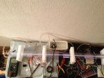
So i got this 60W tube, a 1200mm long bong. It's too long to take a complete shot of it without gluing the camera on the ceiling, so i took 2 shots instead. It needs 22mA of current to produce 60W. Pic 1 shows the business end of the tube, a multimeter registering the tube current (slightly <5mA here), the faint discharge in the bore and a pathetic approximation of a cooling system. It works fine for short (1min or so) bursts at 5-6mA.

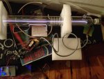
Pic2 shows the anode end and a 'power supply'. The ball of wires and components is a pwm push-pull driver with 2 very good mosfets (they run fine at 5-6A @ 25V w/o any reasonable heatsinking) torturing a small TV flyback transformer with rewound bifilar primary. The HF HV AC from it goes to a TV CRT cascade (voltage multiplier). The output of the cascade, the heavy grey wire, goes to the anote of the co2 tube thru a ballast resistor.
Those flybacks and cascades are only designed to deliver a couple of milliamps. Im really pushing it beyond its limits, but i'll continue doing so until i get a real power supply from china or until it ruptures. I will try putting two cascades in parallel for fun.
As it is now, i can only draw 5.5-6mA max, nowhere near 22mA for 60W.

Even with just 5mA in the tube, it was able to produce a white hot spot on a piece of floor tile /pic 3/. The actual spot is smaller than it appears. From the burn marks on wood, it seems like TEM00 at this power.

Something happened that brought my dormant safety instinct back to life...while i was melting a piece of glass some 60cm from the exit aperture, i saw that the water hose on the OC is smoking. While the glass IS opaque to deep IR, it appears that, when molten, and maybe not only then, it creates specular reflections powerful enough to burn stuff. There is a clear burn mark on the hose.

i'll post more burning pictures once i find a way to pump more current into the tube.
 

Attachments

  • 1.jpg
    1.jpg
    101.8 KB · Views: 371
  • 2.jpg
    2.jpg
    74.4 KB · Views: 404
  • toasting tile.jpg
    toasting tile.jpg
    62.7 KB · Views: 439


Joined
Sep 12, 2007
Messages
9,399
Points
113
Well done. What value of ballast resistor did you use? How well does it work without one?

Glass does reflect some IR. With a thermal camera for example, you can see reflections in plain glass, but you cannot see anything through it.
 
Joined
Feb 1, 2008
Messages
2,894
Points
0
Nice tube and temp psu, have you any specific plans in mind for this one? A CNC cutter perhaps?
 
Joined
Jul 4, 2008
Messages
2,499
Points
113
Nice CO2 laser! Well done on the HV PSU!!
Be extremely careful with longwave IR and make sure you've got a fire extinguisher and googles.
Happy zapping!
 

phenol

0
Joined
Oct 30, 2007
Messages
533
Points
18
Well done. What value of ballast resistor did you use? How well does it work without one?

Glass does reflect some IR. With a thermal camera for example, you can see reflections in plain glass, but you cannot see anything through it.

The ballast is 110k. It works just as well with as much as 400k and as little as nothing. The current doesn't change a lot. I'm assuming that the cascade itself works like a current source due to its apparently large output impedance. Anyway, im not particularly content with this arrangement and i'll be getting a PSU from the laser manufacturer. I contacted them yesterday and they quoted a really nice 10000 hour 80W tube only 1250mm long at under $400, plus some different focal length ZnSe lenses for $40.

I dont know how those power supplies are made, it looks that some of them have 2 HV transformers with combined outputs to a rectifier/multiplier. Or maybe just raw AC on the output?...

As for the glass, it seems that it reflects a lot of IR when molten as it smoked the silicone hose with ease. I'll never put glass in the beam, it's just too hazardous and you never know where those reflections will land...

@Meatball: CNC-no. Cutting and other fun stuff - definitely yes ;) . I'll get a 100mm focal length lens and see what it can do.
 

ped

0
Joined
Nov 25, 2008
Messages
4,889
Points
113
Your using a tripler as the voltage multiplier? (that's what we call them in the UK)

I've replaced hundreds of them in my TV / Video repairman days :D

Not seen one for 15 years!
 
Last edited:

phenol

0
Joined
Oct 30, 2007
Messages
533
Points
18
Your using a tripler as the voltage multiplier? (that's what we call them in the UK)

I've replaced hundreds of them in my TV / Video repairman days :D

Not seen one for 15 years!

Yes, that's what im using. I have a pile of old russian cascades /27kV@1.3mA/. I blew one the other day when i removed the load. Russian forums claim that they can easily withstand 60kV and let out huge sparks, but i somehow doubt that.

i was planning on building my own multiplier with a string of HER108 diodes and HV caps, but such a thing would arc terribly everywhere and waste energy in corona discharges unless potted.
 
Joined
Jul 4, 2008
Messages
2,499
Points
113
Yes, that's what im using. I have a pile of old russian cascades /27kV@1.3mA/. I blew one the other day when i removed the load. Russian forums claim that they can easily withstand 60kV and let out huge sparks, but i somehow doubt that.

i was planning on building my own multiplier with a string of HER108 diodes and HV caps, but such a thing would arc terribly everywhere and waste energy in corona discharges unless potted.

Yes those cascade (triplers) will do 60kV if you allow them
to arc at a distance. Myself seen them arc 6-7cm.
More than 60Kv in large cascades from old color TVs. In circuit maybe only gave 35Kv.
Btw, id be very cautious around cascades. they've claimed many a TV repairmens lives
there is enough current in those cascades to kill you.
Discharge current momentarily is well in the 10s of Amps.
A very tamed version if the tripler is known as a tazer.
 
Last edited:

phenol

0
Joined
Oct 30, 2007
Messages
533
Points
18
I'll parallel two cascades tonight if i find my old stock and see how it fares
 
Joined
Sep 12, 2007
Messages
9,399
Points
113
I dont know how those power supplies are made, it looks that some of them have 2 HV transformers with combined outputs to a rectifier/multiplier. Or maybe just raw AC on the output?...

The design isn't too dissimilar from yours. Pretty much a TV flyback (or two in parallel) with current regulation. I didn't see any multiplier on the one I have, but it may be integral to the transformer.
 

phenol

0
Joined
Oct 30, 2007
Messages
533
Points
18
But the output is rectified, right? And hopefully also filtered to a practical level attainable with capacitors at 30-40kV.
in the meantime, i reduced the number of windings in the primary and was able to get nearly 10mA in the tube at the expense of dramatic increase in primary side current drain and xfromer core heating.
Since those tv flybacks are air-gapped, they spew massive amounts of magnetic interference. i couldnt separate the two ferrite halves in order to remove the plastic spacer.
While playing with the PWM frequency, i happened to cross the resonant freq of the flyback secondary. the effect is that of a well tuned mini tesla coil. if left free-running, it would have bursted into sparks and then flames if it werent properly potted.
 
Joined
Sep 12, 2007
Messages
9,399
Points
113
It's definately DC. I don't know how smooth it is, but the tube shouldn't care too much.
 

phenol

0
Joined
Oct 30, 2007
Messages
533
Points
18
It's definately DC. I don't know how smooth it is, but the tube shouldn't care too much.

well, the feedback loop might...

anyway, i guess i'll see for myself because i ordered a 60-80W brick (and a znse FL=100mm lens)


Top