Welcome to Laser Pointer Forums - discuss green laser pointers, blue laser pointers, and all types of lasers

LPF Donation via Stripe | LPF Donation - Other Methods

Links below open in new window

ArcticMyst Security by Avery

JDS Argon is not doing 60mW. Tweaking questions.

Joined
May 29, 2013
Messages
7
Points
1
I have a JDSU Mod 2011 65ML argon laser I cadged from an NIH warehouse, but when run on light feedback mode, I can only get about 15-25mW multiline from the argon (varies which meter (Si/bolo) is reading it). It is in an older Leica confocal microscope I have pretty well resuscitated. The unit may have overheated (limit) on idle a couple times. The tube only has about 1500hours, but wondering if there is any thing I should do. I am a very poor lab rat researcher with sequestration. Its on a big fan, runs stable, just never increasing past 15mW at 7V on the 0.1V/mW regulation of pin 7. Starts fine, runs stable if not over 9V on pin 7.
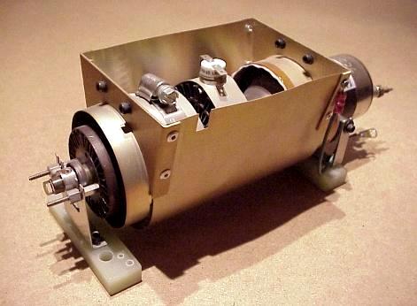
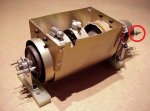
Inside I has this style head, with a funny ring on the front end...
cutube1.jpg


Questions:
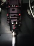
1. Tweaking the JDSU laser unit head, like adjusting the mirrors/brewster prisms/screws. Anyway to do this safely? My beam seems to be coming out very angled, and low power. Will this increase optical power. The rear of the unit seems to just be a mirror.
mirwalk1.gif


2. I was advised to check the filament voltage..how to do this on a JDSU supply, I only see current and light output regulation?

3. Try another supply, I was advised sometimes the JDSU supplies die. Where to get another that will drive 65mW or more, on the cheap?. I guess it has to be fairly stable for confocal work...:thinking:

4. Turning the optical power pot, the light output increases rapidly..and then never goes farther..up to 7V on pin7. Does this tell you my problem?


Joined
Dec 31, 2012
Messages
904
Points
0
1. I am surprised you can even see the amount of skew coming from the laser. I tried to find the specs on the bore diameter, because what you are describing seems unlikely, given the bore diameter is smallish. Presuming your diagram accurately depicts what is going on inside the laser, my hunch is there just isn't enough room in the bore for a beam to lase askew and emit at an angle large enough for you or me to detect.

With that said, if it is doing (internally) what you describe, the only way I know how to correct the HR mirror is a full alignment, which means pulling the OC mirror off, and using a procedure similar to that discussed on Sam's website repairfaq.org. In that procedure, one shines a HeNe into the open end of the laser from across the room, and one attempts to adjust the HR until it shines right back into the HeNe.

Is it possible that the feedback optics, the one's that tell the PSU what power the laser is emitting, is it possible that assembly is skewing the output beam?

2. Again, refer to Sam's website for schematics. If memory serves, the filament voltage is the voltage that approached 500VDC, so make sure you have appropriate test equipment. I'm not sure what the voltage will tell you, if she lases and responds to light output changes at the pot.

3. The JDSU 2210 PSUs are pretty common place. I've purchased a few from eBay. I own several. Again, if your tube fires up immediately, has the low hours you're suggesting, it may not be the supply. But either buying one or finding someone with one of these heads so you can borrow one is your best bet. If you're going to pay to have one shipped to you (on loan) you may as well buy another. For the cost of return shipping may cover the bulk of the cost for a second PSU.

4. Does not 7.0V indicate 70mW ? Do you have an LPM to test the output and see a second opinion? If she is outputting 70mW, that may be the limit.

The size of the tube pictured looks very similar to the JDSU 2214 family of air-cooled Argon Ion lasers. As such, these (ML) are rated for (at most) 35-40mW. While I own some tubes from this family that emit powers in the 80mW and 120+mW, they only do so fully cranked up. And at full power, the tube life is rated for only a few hundred hours. Back the power back down in the 6A range, and they emit around 40mW, just what they are rated for, with 1000s of hours of run time expected. These numbers refer to ML models. SL (single line) models will output much lower, depending on the wavelength.
 
Joined
Sep 12, 2007
Messages
9,399
Points
113
2. Again, refer to Sam's website for schematics. If memory serves, the filament voltage is the voltage that approached 500VDC

Not even close :p

The filament voltage is simply the voltage across the filament. Set your meter to AC volts, and measure across the two terminals coming out of the back. It should be somewhere around 2.7V.

This terminal, and the one next to it (out of view):

attachment.php


Does not 7.0V indicate 70mW ?

No, pin 7 is light adjust. Pin 8 (or sometimes pin 9, evidently) is the power reading.

Op: measure the voltage on pin 8, multiply it by 10, and that should give you an accurate power reading. Also report on what pin 9 reads, if you please.
 

Attachments

  • Untitled.jpg
    Untitled.jpg
    48.4 KB · Views: 374
Last edited:
  • Like
Reactions: ped
Joined
May 29, 2013
Messages
7
Points
1
Power Measurements: Fluke DMM.

OK, Here is what I get using Pin 11 Return (Gnd Circuit). Mega air cooling.
  1. Idle: Pin 8 0.87VDC Pin 9 0.40VDC Pin 7 command volt:0V
  2. Full: Pin 8 4.53VDC Pin 9 0.68VDC Pin 7 command volt 4.74VDC (~47mW).

It seems to be peaking in power output early on the light drive of pin7 if this helps. :undecided: And the beam exits very angled down, as I had to redrill KineFLEX to get the fiber align controls anywhere near the beam.

I have not measured the filament voltage yet. Open case to do after lasing, with good insulation?
 
Joined
Sep 12, 2007
Messages
9,399
Points
113
According to those readings, what you call "full" is only 6.8A of tube current. As I understand it, something around 8A is the best trade-off between power and tube life, but they can handle up to 10A or so. You can try increasing the voltage to pin 7 a bit and see if that changes anything, or you can switch to current-mode operation.

I don't think you need to measure filament voltage; everything looks in order except for the exit angle. I'm not sure what to make of that. Picture?

If you want to measure it anyway, turn the laser off (shutdown mode or whatever), but leave everything plugged in. The filament will usually remain ON even when the laser is off. It will create minimal heat in this mode, so it is safe to remove the cover and cooling.
 
Last edited:
Joined
May 29, 2013
Messages
7
Points
1
I am trying to cook it at mid power for a day at 13mW to see if it outgasses, or should I say degasses? Add more power does nada right at the moment.

At first when I got this unit, I used the Leica front panel argon laser power control which can take pin 7 on the JDSU power supply DB25 up to 15V. When the laser got around 10V or more it started to make a "chattering" noise, and I immediately cut the power. After all 10V is commanding the unit to go 100mW, when my 65ML tube is only rated 65mW.

So I installed a limiter pot in series with the control pot to not allow the power control voltage to get into the chatter region, where I am not sure what is happening but when it chatters, it sounds like it could damage the tube. Lasing is unstable? :undecided: Argons are reported to run longer when at lower power anyway, (although above idle).

OK, the overnight cooking verdict (with cooling). NADA.

In the AM the beam was still at 13mW, it did not change a bit from 13mW.

The AC filament voltage on the unit reads 2.8VAC at start (non lasing) and when heated runs about 2.78VAC (non-lasing).

So what to do to bring this baby anywhere near JDSU Mod 2011 65ML rated 65mW? I could live with 30mW, really.

http://laserpointerforums.com/images/smilies/thinking.gif

The back mirror (near the filament looks a little saggy), not sure if these guys move, or can you move them safely. The unit has 1500 hours but maybe was run hard? Or maybe the filament sagged from overheat a couple times on idle.

Fooled by silicon detector power meter saturation...
Well, I was about to give up, and started mounting the optical fiber on it.

Aligned the fiber...and the output of the fiber was again 13mW! Now.... How did I not lose any power through the optical fiber...I got to thinking .


...It was this guys Silicon Detector on a 1930C Newport Power Meter I borrowed. Apparently at 488nm it saturated at 13mW, but it did not tell you. Sliding the 3.0 OD ND filter in the head made it read 35mW output out of the fiber, and probably more straight from the laser (but I wish to avoid realigning polarized optical fiber). Now that is more like it, and I can probably work with this on my confocal microscope if I carefully align things.


So I learn, don't trust Si detectors for power readings. They are fast and sensitive though, but they saturate in wierd ways. Back to bolometers I guess.


So thanks everybody for your help.
I usually work with irradiance and lux, so power measurements are a little foreign to me with lasers.
 
Last edited by a moderator:
Joined
Dec 11, 2011
Messages
4,364
Points
83
How about running the laser in Current mode and setting the current to 7 to 9.5A (the normal safe operation range)?
 
Joined
Dec 31, 2012
Messages
904
Points
0
How about running the laser in Current mode and setting the current to 7 to 9.5A (the normal safe operation range)?

9.5A seems a bit high, to me. But the 6-7A range is a great compromise between tube life and output. Consider the following chart (courtesy Sam's Repair FAQ site) for the ALC 60X Air-cooled Argon Ion Laser, much like these JDSU units.

Code:
 Tube	------- Output Power --------
Current	All nm 	457nm	488nm	514nm	Lifetime (Hours)
4A	10mW	1mW	7mW	0mW	15,000-25,000 Hours
6A	30mW	2mW	17.6mW	7.5mW	8,000-15,000 Hours
8A	70mW	5mW	27mW	23mW	4,000-6,000 Hours
10A	130mW	10mW	44mW	42mW	1,500-2,000 Hours
12A	200mW	15mW	60mW	68mW	1,000-1,500 Hours
14A	280mW	22mW	81mW	98mW	500-1,000 Hours

Observe that at 4A, tube life could be as low as 15,000 hours. But at 10A, only 1,500, and at 14A, 500 hours. The curve really begins to ramp up over 8A.
 
Joined
May 29, 2013
Messages
7
Points
1
I think the JDS laser DB25 connector is set by Leica to regulate light output to the beam scan head on the microscope. For microscopy, this ensures the beam intensity at the specimen stays uniformly bright. I put in a variable limit resistor in series with their argon laser 10K power intensity pot on the front cabinet panel, to allow about 70mW max. So far so good and no chatter.

Now the beam is out of the AOTF, and into another polarized fiber to the microscope scan head. It seems to need aligning in the scan head. Lots of red marked screws here.
 

Attachments

  • ScanHeadAlign_2013-06-28-191715b.jpg
    ScanHeadAlign_2013-06-28-191715b.jpg
    68.2 KB · Views: 243
Last edited:

diachi

0
Joined
Feb 22, 2008
Messages
9,700
Points
113
With that said, if it is doing (internally) what you describe, the only way I know how to correct the HR mirror is a full alignment, which means pulling the OC mirror off, and using a procedure similar to that discussed on Sam's website repairfaq.org. In that procedure, one shines a HeNe into the open end of the laser from across the room, and one attempts to adjust the HR until it shines right back into the HeNe.

Is it possible that the feedback optics, the one's that tell the PSU what power the laser is emitting, is it possible that assembly is skewing the output beam?

2. Again, refer to Sam's website for schematics. If memory serves, the filament voltage is the voltage that approached 500VDC, so make sure you have appropriate test equipment. I'm not sure what the voltage will tell you, if she lases and responds to light output changes at the pot.

The optics on these tubes cannot be removed ( Well they can ... but the tube would go up to air... ) - they are hard sealed - you can attempt to adjust them by "bending" them while the tube is running using an insulated rod ( I've used BIC pens with the ink tube removed ) - The OC mirror on these is connected directly to the anode, so it's sitting at up to 100-115VDC when the tube is running.

Filament voltage on these is usually 2.6-2.8VAC.


9.5A seems a bit high, to me. But the 6-7A range is a great compromise between tube life and output. Consider the following chart (courtesy Sam's Repair FAQ site) for the ALC 60X Air-cooled Argon Ion Laser, much like these JDSU units.

Code:
 Tube    ------- Output Power --------
Current    All nm     457nm    488nm    514nm    Lifetime (Hours)
4A    10mW    1mW    7mW    0mW    15,000-25,000 Hours
6A    30mW    2mW    17.6mW    7.5mW    8,000-15,000 Hours
8A    70mW    5mW    27mW    23mW    4,000-6,000 Hours
10A    130mW    10mW    44mW    42mW    1,500-2,000 Hours
12A    200mW    15mW    60mW    68mW    1,000-1,500 Hours
14A    280mW    22mW    81mW    98mW    500-1,000 Hours
Observe that at 4A, tube life could be as low as 15,000 hours. But at 10A, only 1,500, and at 14A, 500 hours. The curve really begins to ramp up over 8A.


8A is the widely accepted maximum safe current for these JDSU units.You can run at more than that, but tube life decreases somewhat significantly. 8A is a good trade-off.

Also the ALC-60 while air-cooled and similar in size is not as "rugged" as the JDSU tubes. The filament isn't as tough, the mirrors aren't sealed, etc.

I think the JDS laser DB25 connector is set by Leica to regulate light output to the beam scan head on the microscope. For microscopy, this ensures the beam intensity at the specimen stays uniformly bright. I put in a variable limit resistor in series with their argon laser 10K power intensity pot on the front cabinet panel, to allow about 70mW max. So far so good and no chatter.

Now the beam is out of the AOTF, and into another polarized fiber to the microscope scan head. It seems to need aligning in the scan head. Lots of red marked screws here.

Is the beam coming out at an angle from the AOTF or is it like that directly from the aperture of the head?

If it's coming out like that directly from the aperture it could either be that the feedback optics ( as suggested before ) are skewing the beam or the tube isn't sitting straight in the head.

If it's coming out at an angle from the AOTF then that's normal.

aotf.gif
 
Last edited:
Joined
May 29, 2013
Messages
7
Points
1
My JDS end has a black mount that has an output hole that sort of looks like a keyhole. The multiline argon beam is coming out at a slight down angle (<5 deg), and I finally found a KineFlex position of the coupler where the alignment screws could couple to it. So since my watt emission issue was a meter saturation issue underreporting the performance, I am not going to mess with the JDS tube mirror ends.

My laser end looks like the previous picture, and I cannot put an empty BIC pen around it as it is about 12mm in diameter at the mirror. (I did try pushing the mirror slightly with a Delrin rod, but it is very rigid).

For AOTFs, what you said about the 2 beams is correct. The straight one is modulated by the unit, and the other comes out at a diving angle. I have coupled the correct modulated beam to the fiber optic here.

The fiber optic output of the AOTF is heading into this complex head on my confocal scanner module, where I have shown the coupler in the photo. Wish me luck with the screws (avoiding the red ones).
confocalmic_large.jpg
--I have the single visible laser input, 2 PMT version of this head.


Top