Welcome to Laser Pointer Forums - discuss green laser pointers, blue laser pointers, and all types of lasers

LPF Donation via Stripe | LPF Donation - Other Methods

Links below open in new window

ArcticMyst Security by Avery

Why don't we use op-amp current sources?

Joined
Dec 7, 2010
Messages
9
Points
0
^
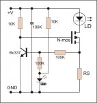
Just for curiosity, what are you using as Rsense ? ..... the current shunt of the amperometer ? (at those currents is the more cheap solution, usually)

im using two 50watt 0.01 ohm power resistors in parallel ( 0.005ohm ). i think cheap solutions are generally more expensive than expensive solutions...:)


Joined
Aug 15, 2009
Messages
1,443
Points
48
It can work this way, but it's not the best option. There will be 0.6~0.7V across R2, which is still quite some power at 8A. Just use an opamp, you can make the sense resistor as small as you want untill you meet the noise level, and an opamp has far better feedback than this circuit. Plus an opamp circuit can easily be adjustable without needing other high power resistors of different values.
 
Joined
Oct 26, 2007
Messages
5,438
Points
83
Ah, thanks for catching that. This is more like it.

(image)

If you're going to do that you might as well forego the transistor completely.

The thing is, I need to avoid using a circuit that relies on a very high power sense resistor. This is for high currents! 5-20A

Now with an IRFP250, a current of up to 8A, and a supply voltage of 12V, the resistor would STILL be dissipating lots of power... wouldn't it?

Here's another one you could try. It is trim-pot adjustable, and the sense resistor needs to be 0.2V / Amps rather than 0.58V / Amps as in the other one. That would mean a 0.01 ohm resistor, which you can buy for about $5.

If you don't want to spend that much for a single resistor or can't find resistors that can handle that, you can also make a current multiplier by just replicating the current sink circuit and tying the drains together.
 

Benm

0
Joined
Aug 16, 2007
Messages
7,896
Points
113
It just looks like a very easy current source based on an o amp with a feedback for regulation. What do you guys think? Why haven't we seen more of these around the forum?

I have no clue why people insist on using LM317's and similar chips to build current sources around here. Personally i always use the opamp approach, aided by a power transistor to handle the actual current.

The performance of these drivers is great, they are rock solid and don't need output capacitors to stabilize the regulator. Although i would not recommend it, i've at several times hot-swapped the laser diode without any ill effect. Do that on a 317 based driver and your diode is toast.

As for the voltage drop: This can be very very low, way below the very best voltage regulating chips abused as current sources. You can work with a reference of 0.1 volts, and a FET as the power driver. Voltage drop across the entire thing would be 0.5 volts or so. But even using a 0.7 volt diode reference and plain NPN power transistor, the minimal voltage dropout is 1.1 volts or so - far better than any voltage regulator based design can ever hope to achieve.

The only downside is with portable red diode lasers: Since the negative lead of the diode is not connected to ground, designing the host will be more difficult. I suppose this reason alone is enough for people not to give it a go.
 

HIMNL9

0
Joined
May 26, 2009
Messages
5,318
Points
0
I have no clue why people insist on using LM317's and similar chips to build current sources around here.....

..... Easyness ? ..... one IC and one resistor, and you're done ..... ;)


The only downside is with portable red diode lasers: Since the negative lead of the diode is not connected to ground, designing the host will be more difficult. I suppose this reason alone is enough for people not to give it a go.

This is true for sink designs, but remember that also source designs exists, and they have common ground ..... sink designs was preferred only cause they uses N-channels mosfets, more easy and cheap and with better RdsON, but with the new products, is easy to find also P-channel fets with decent characteristics and good prices, now (i'm waiting for some IRF4905 for build a serie of source drivers for a commercial application, as example, and they hold more than 70A at 55V with an RdsON of 20 milliohms ..... still higher than a N-channel one, but very good, compared with older components).
 

Benm

0
Joined
Aug 16, 2007
Messages
7,896
Points
113
I suppose you could build a source design if you wanted to - its just that most textbook current sources are designed as sinks.

I haven't tried it, but it should be perfectly feasible to 'mirror' the entire driver with the reference from the positive supply and the sense resistor and fet/transistor coming down from supply. One thing that could complicate these designs is that you require an opamp that has a common mode input range that extends all the way to the positive supply rail. Most TL08x will actually work, but its by no means within guaranteed specs of many common opamps.
 
Joined
Oct 26, 2007
Messages
5,438
Points
83
..... Easyness ? ..... one IC and one resistor, and you're done ..... ;)

Yeah, that's probably the main reason. People have a hard enough time figuring out Ohm's Law. Ask them to read how op-amps work, or how to regulate the current on a transistor and they get scared.
 

Benm

0
Joined
Aug 16, 2007
Messages
7,896
Points
113
I suppose so - for the voltage regulator used as current sources its just a matter of 'solder this resistor there' and be done with it.

Opamp based current sources and sinks require a lot more connections to be made, even if you follow a ready made schematic to build them. Surely the aren't for people with zero experience in electronics, but i see people using those designs that do have a good idea what they are doing too.

I do notice that people use voltage regulators way out of specification though. If you abuse a LM317 as a current source, you should require both 1.25 volts drop in the reference, AND 3 volts drop between input and output for reliable operation. Effectively this means that the design is not solid even when powering a red diode from 2 lithium cells. Most voltage regulators will work below the guaranteed specifications, but if see people posting complaints or questions about it, the answer can be quite simple: you're doing it wrong!

Such things may be very frustrating too, because a solution with one LM317 chip can work for one builder, but fail for another. There seems to be no apparent mistake or reason, apart from using the component outside of its specifications in the first place.
 
Joined
Feb 1, 2008
Messages
2,894
Points
0
It can work this way, but it's not the best option. There will be 0.6~0.7V across R2, which is still quite some power at 8A. Just use an opamp, you can make the sense resistor as small as you want untill you meet the noise level, and an opamp has far better feedback than this circuit. Plus an opamp circuit can easily be adjustable without needing other high power resistors of different values.

Ah, so the opamp circuit uses an Rsense which is not nearly as beefy?
 
Joined
Oct 26, 2007
Messages
5,438
Points
83
Well, depending on how you tune the circuit the resistance of Rsense can be lower, but it's not the only way to accomplish it. You can use the mosfet + NPN method too, or the constant dimmer circuit, which requires a 0.2V drop across Rsense.
 

Benm

0
Joined
Aug 16, 2007
Messages
7,896
Points
113
Surely true. You can use sense resistors as low as 0.1 ohms with proper opamp drivers, resulting in a current dissipation 100 times lower than comparable lm317 desings.
 
Joined
Feb 1, 2008
Messages
2,894
Points
0
Lets compare the FET method and the opamp method.

The opamp is more flexible, and can be tuned to read very low resistances?

The FET method just seems easier to construct, and easier to buy parts for since R and P values are only factors of the current through them.

Stability is important, but if you viewed the transients on a scope, would there really be a significant difference?

How fast would an NPN be able to respond to controlling the Gate, if the Gate will be instantly and initially told to conduct completely? Perhaps an opamp IC wouldbe able to respond faster? Resulting in fewer diode deaths?
 

HIMNL9

0
Joined
May 26, 2009
Messages
5,318
Points
0
You can try a modified version of the fet type driver, that i designed years ago for leds ..... but be careful and do some tests, first, cause i had designed this version only for use it with LEDs, and also if it worked good with LEDs, i never tested it before with LDs.

attachment.php


EDIT: Sorry, typo, i drawed it on-the-fly from my "paper and pencil" archive copy, and indicated the capacitor as "100K", where instead is ofcourse "100nF" ..... you can also "play" with the values of the resistor couples, for try to "tune it" for the lowest dropout possible on the RS, depending from the power supply (indicatively, keep the value of the couple of 10K from 19K to 33K, and the value of the 100K couple from 80K to 120K ..... in the better conditions, you can get also just 0.1V of dropout, but it become a bit critical at that value ..... and ofcourse he current depend from this too ;))
 

Attachments

  • basical low dropout driver.jpg
    basical low dropout driver.jpg
    36.2 KB · Views: 4,865
Last edited:

Benm

0
Joined
Aug 16, 2007
Messages
7,896
Points
113
I was thinking about an opamp design with a FET as the current passing component instead of a bipolar transistor, so its a hybrid of the circuit above and the basic opamp design.

As for the driver speed: One pitfall could be using a fet with a very low RDSon, which typically have large junctions and hence large gate capacitance. The opamp driving it should have resonable source and sink capabilities to make the entire driver fast.

This speed issue is only important if you want to be have to swap the diodes hot, or have unreliable connections. Under normal circumstances it is not problem if the driver responds a bit slower to load changes.
 

HIMNL9

0
Joined
May 26, 2009
Messages
5,318
Points
0
I was thinking about an opamp design with a FET as the current passing component .....

Sorry, maybe i'm misunderstanding, but this is the basical configuration of the sink design, already ..... or you are referring about sources ?
 
Joined
Feb 1, 2008
Messages
2,894
Points
0
You can try a modified version of the fet type driver, that i designed years ago for leds ..... but be careful and do some tests, first, cause i had designed this version only for use it with LEDs, and also if it worked good with LEDs, i never tested it before with LDs.

attachment.php


EDIT: Sorry, typo, i drawed it on-the-fly from my "paper and pencil" archive copy, and indicated the capacitor as "100K", where instead is ofcourse "100nF" ..... you can also "play" with the values of the resistor couples, for try to "tune it" for the lowest dropout possible on the RS, depending from the power supply (indicatively, keep the value of the couple of 10K from 19K to 33K, and the value of the 100K couple from 80K to 120K ..... in the better conditions, you can get also just 0.1V of dropout, but it become a bit critical at that value ..... and ofcourse he current depend from this too ;))

It looks like the same basic sink type regulator, but with a voltage divider with an LED tapped into it, and then there is a resistor on the emitter.

What's the purpose of this resistor? Doesn't it affect the Vbe of the NPN?


Top