Welcome to Laser Pointer Forums - discuss green laser pointers, blue laser pointers, and all types of lasers

LPF Donation via Stripe | LPF Donation - Other Methods

Links below open in new window

ArcticMyst Security by Avery

Unexplainable problem with DDL Circuit ~PICS NOW~

Cxrazy

0
Joined
Aug 15, 2007
Messages
179
Points
0
Hey guys,

I'm having real trouble figuring this out.

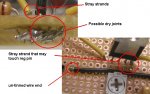
So I built the cicruit, and I used an NTE956 regulator, as the LM317 I had did the same thing, so I believed it was faulty. Its the same chip, just by a different company.

My problem is this:

When I measure my mV, which would give me my mA, across a 1ohm resistor in series with a 100ohm load I have in place of a laser diode, I get a stable output ~41.4mV (this is for a bluray) This doesn't change in any way.

I then put my bluray diode in place of the 100ohm load, you'd think everything would be fine right? WRONG.

I get ~41mV right when I plug it in, but then it slowly drops... and drops... and drops... until it reaches zero. What is the problem here?

Is something wrong with my diode?

I uploaded a video, and the dot is BARELY visible on my hand, it looks very brihgt in the video however. I took it with my phone, so forgive the quality.
 

Attachments

  • Laser.mpg
    724 KB · Views: 53


Joined
Oct 30, 2007
Messages
137
Points
0
Re: Unexplainable problem with DDL's Circuit. HELP

Hey, get with LarryQ. I had the same problem and He was able to look at my circuit and fix the wiring. I read the schematic and built what I thought was correctly but I misinterpretted it.
Larry saved the day and I am very impressed with his knowledge and willingness to help. Catmandoo
 

Benm

0
Joined
Aug 16, 2007
Messages
7,896
Points
113
Re: Unexplainable problem with DDL's Circuit. HELP

That's odd indeed. To make 100% sure, you could repeat the experiment while measuring the voltage across the laser diode. This should also drop over time, but not as fast as the current.

How much voltage are you feeding the regulator anyways, and does it get warm at all?
 

Cxrazy

0
Joined
Aug 15, 2007
Messages
179
Points
0
Re: Unexplainable problem with DDL's Circuit. HELP

its getting 9v from a wall DC converter majigger. The regulator doesn't get warm. It works fine with the 100ohm resistor, but flakes out with the LD, so its not a thermal problem.

Oh LarryQ, come read my post!
 
Joined
Oct 28, 2007
Messages
2,631
Points
48
Re: Unexplainable problem with DDL Circuit ~PICS N

Cxrazy said:
http://s3.photobucket.com/albums/y57/cxr_azy/Laser/

Hopefully that works.

ANYONE see anything that looks wrong? PLEASE!

I talked to you over laserchat, tell me if My suggestion worked
 
Joined
Aug 18, 2007
Messages
114
Points
0
Re: Unexplainable problem with DDL Circuit ~PICS N

Cxrazy said:
http://s3.photobucket.com/albums/y57/cxr_azy/Laser/

Hopefully that works.

ANYONE see anything that looks wrong? PLEASE!

eww that looks horrible IMO

You are supposed to solder to the copper contacts on the perfboard then run wire to the other components.
 
Joined
Nov 24, 2007
Messages
321
Points
16
Re: Unexplainable problem with DDL Circuit ~PICS N

Hey - I know that the behavior you describe *CAN* happen if you get pins 2 & 3 reversed on the LM317. Out & Adj. There are a couple of schematics in the archives that have this problem, and if you build according to those, you will get a good current peak as you increase the pot current setting, but the current will then diminish once you stop increasing the pot current setting (ie., decreasing the resistance). Take a good look at the schematic vs. the "visual connection diagram" (VCD) on the DDL driver sticky. The VCD is correct - pin 3 should be a direct connection to the LD. If pin 3 is going through resistors, it's reversed.

Let me know if this helps...

Dave
 
Joined
Jul 24, 2007
Messages
2,749
Points
0
Re: Unexplainable problem with DDL Circuit ~PICS N

Have you measured the input voltage from the walmart PS whilst the LD supply is going down? Does it stay stable? I cannot think why it should be different whether used with a dummy load or the LD but worth checking.

Just a helping hand here, you have your protoboard upside down, put the components in from the blank side and solder them to the pads underneath, leave all the component legs long and bend them to spread them out, you can then solder your wires to the long legs for initial testing. Once you have that done you can tidy it up.
The other thing that is very noticable on the photo's are what would be called dry joints and stray strands. the main reason you have these is that you have not tinned your wire ends before soldering to the circuit.

I am not having a pop at you, we all had to learn how to do this...it is a skill that comes with practice. Keep at it you will get there ;)

Regards rog8811
 

Attachments

  • XC_circuit01.jpg
    XC_circuit01.jpg
    170.7 KB · Views: 7,480
Joined
Aug 18, 2007
Messages
114
Points
0
Re: Unexplainable problem with DDL Circuit ~PICS N

I hate using vero or perf board, no matter how hard you try it still looks crap and de-bugging it can be a bitch.

Its so much easier to draw on a blank PC board with a etch pen and drop it in some HCl + h202 to etch it, only annoying thing is drilling the holes but its worth it when you get a professional board that wont fail a few months down the track.

I should post a tutorial somewhere.
 
Joined
Jul 24, 2007
Messages
2,749
Points
0
Re: Unexplainable problem with DDL Circuit ~PICS N

I have never used perf board, I was brought up on vero so it comes as second nature to me :) In the days before CAD I used to design and lay out double sided boards, on acetate in blue and red tape. It never taught me anything about electronics though, I have got much of that knowledge from forums like this :).

@cXrazy, I used a term above that could use a bit of explanation. I have done a quick video of prep'ing and tinning a wire ready for attaching to a circuit. one explanation I need to add is there is one bit where I say "flick it" meaning flick the wire. It is just something I have always done when the solder is still hot to remove any excess. That way the wire doesn't end up with a blob of solder on the end which will stop it going through the hole in the circuit board.

Again I hope this is helpful to you ;)

Regards rog8811
 

Attachments

  • tinning01.wmv
    4.4 MB · Views: 64

Cxrazy

0
Joined
Aug 15, 2007
Messages
179
Points
0
Re: Unexplainable problem with DDL Circuit ~PICS N

I know it looks like crap. I wasn't worried about it, so I put it together to see if it would work. I was planning on rebuilding it.

I would love to begin etching my own boards, but that seems like an adventure of a completely different type.

I believe my problem is the fact that I am using a wall adapter to supply 9v to the circuit. I've tried the LD with 2xCR123 batteries and it was stable, the current and voltage was too low because it needs another one. My problem was the PS I was using, and hopefully adding a 3rd CR123 will give me a stable bluray. Yes the circuit is ugly, but its correct, and its gonna be in a box anyway, ;D

Anyone know where I can get a 3xCR123 holder? As well as a nice case to put the circuit/laser/batts in?
 
Joined
Oct 28, 2007
Messages
2,631
Points
48
Re: Unexplainable problem with DDL Circuit ~PICS N

Cxrazy said:
I know it looks like crap. I wasn't worried about it, so I put it together to see if it would work. I was planning on rebuilding it.

I would love to begin etching my own boards, but that seems like an adventure of a completely different type.

I believe my problem is the fact that I am using a wall adapter to supply 9v to the circuit. I've tried the LD with 2xCR123 batteries and it was stable, the current and voltage was too low because it needs another one. My problem was the PS I was using, and hopefully adding a 3rd CR123 will give me a stable bluray. Yes the circuit is ugly, but its correct, and its gonna be in a box anyway,  ;D

Anyone know where I can get a 3xCR123 holder? As well as a nice case to put the circuit/laser/batts in?

W0000000000000TS I FEEL SPECIAL

Your the second person ive helped to fix a problem on this forum... Now thime to try and fix my own problems... ::)

I havent even found a 2x CR123 holder, if you know of one please tell me. The only ones Ive found are single CR123 holders (AKA 2/3A holders) and I was thinking about buying 3 and hooking them up in series...

regards,

amk


Top