Welcome to Laser Pointer Forums - discuss green laser pointers, blue laser pointers, and all types of lasers

LPF Donation via Stripe | LPF Donation - Other Methods

Links below open in new window

ArcticMyst Security by Avery

Understanding the Fusion Driver

z000z

0
Joined
Jan 22, 2008
Messages
50
Points
0
Since I have a few of these, but the potentiometer is rather crap, I'm trying to understand how this circuit works. Specifically how the resistors effect the ma.

I understand how the DDL circuit works where you have just an LM317 voltage regulator, the regulator tries to keep a 1.25 VD between adj and out, so to get the I of the V= IR, you substitute I = V/R, so a 4 ohm resistor = 1.25/4 = 0.3125 amps.

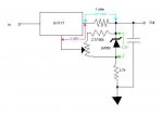
But the Fusion driver seems to be doing something more complicated than that. It has a voltage regulator like DDL's driver (except it uses a TLV1117 instead of a LM317, but I think that's just for efficiency), but it also has something called an Adjustable Micropower Voltage Reference (LM385).

From what I can tell a voltage reference is something like a voltage source, always outputting 1.25v, so assuming that the LM385 is always outputting 1.25v. The thing I'm not quite understanding is how the blu (100k) or red (2.4k) resistors are effecting things.

It appears that the only things in the path of the adj pin on the TLV1117 are the LM385 and the 1k potentiometer (which seems like a rather large value for the max of the potentiometer, 100 (min 12.5 ma) ohm or even 50 (min 25 ma) ohm seems like a good max)


I'm hoping maybe someone can explain what's going on with the 100k/2.4k resistors?


Joined
Sep 8, 2008
Messages
182
Points
0
z000z,

The LM385 simply gives a voltage reference (either 1.2 or 2.5V depending on model) anode to cathode. The TLV1117 always presents 1.25v between out and adj terminals. So assuming that this circuit uses the 1.2v LM385, that leaves 0.05v across the 1 ohm resistor at the minimum POT adjustment, giving 50mA. (Don't know the size of the pot so I can't tell you the max.) But the resistor chosen for the 2.7/100k spot sets the max current allowed by the circuit. (The other 2.7k between diode and ground just controls how much current the voltage reference gets.)

I've attached a schematic that I think is right. If anyone sees mistakes with it, please speak up...

Hope this helps.

cheers,
kernelpanic

[edit] Just saw the pot is 1k in your previous post. I calculate the max current as follows-
At R=2.7k - 50 < I < 425mA
At R=100k - 50 < I < 62.5mA

(This seems a little odd to me, for PHR803T's it seems like 33k or 47k would be better...)
[/edit]
 

Attachments

  • fusion_001.JPG
    fusion_001.JPG
    14.2 KB · Views: 3,089
Joined
Aug 15, 2007
Messages
1,880
Points
0
Any questions - ask drlava. He provided the initial schematic.
The way I understand it, instead of like the LM317 having a 1.7v drop across the sense resistor as its control, this has a 1.25v reference to control it. Adjusting the resistor adjusts how much of this the driver gets, and it thus adjusts current to compensate.
 

z000z

0
Joined
Jan 22, 2008
Messages
50
Points
0
Thanks,

Kernelpanic, if you don't mind could you explain a little how you calculated the max current numbers?

I tried assuming that the potentiometer was set at 0 ohms, and that 1.25v was going over the 2.7k or 100k resistor, but that should be 1.25/2700 = 0.46 ma, and 1.25/100000 = 0.0125 ma

I'm figuring I'm just not remembering something from electronics (been awhile)
 
Joined
Sep 8, 2008
Messages
182
Points
0
z000z said:
Thanks,

Kernelpanic, if you don't mind could you explain a little how you calculated the max current numbers?  

I tried assuming that the potentiometer was set at 0 ohms, and that 1.25v was going over the 2.7k or 100k resistor, but that should be 1.25/2700 = 0.46 ma, and 1.25/100000 = 0.0125 ma

I'm figuring I'm just not remembering something from electronics (been awhile)

Here's how I calculated it-

The 2.7k/100k resistor and the pot are a voltage divider in series across the LM385 which is a 1.2 volt voltage reference. The LM1117 will supply voltage until the Vref is 1.25v. So with the wioer of the pot turned all the way down, the difference(0.05v) presents across the 1 ohm resistor, giving 50mA. Turn the wiper up all the way and you get a voltage difference and hence amperage of ((1.2 *1000) / (2400 + 1000)) + 0.05 or around 402mA with the 2.4k resistor. For 100k the math is- ((1.2 * 1000) / (100000 + 1000)) + 0.05 for only 62mA max. That's why I wonder about that value. It seems to me 10k would be better for the PHR803T's as that would give ((1.2 * 1000) / (10000 + 1000)) + 0.05 or 159mA max. But perhaps my math is wrong...

At any rate, that's how I calculated the max current. I am curious whether these numbers agree with reality. To anyone who has one of these, what are the min-max current values you've measured with each resistor?

cheers,
kernelpanic
 

z000z

0
Joined
Jan 22, 2008
Messages
50
Points
0
Thanks!

It was originally designed for the kes400a diode, which 62ma max would be a fairly decent max for.

I replaced the potentiometer with a 5k potentiometer (since the one I had was broken)
I was getting odd values of 1.1 to 0.9 ma or so once I did that with the 100k resistor in place.


Which going by that math I believe would be:
((1.2 * 5000) / (100000 + 5000)) + 0.05 = 107ma max

The odd thing though was that I was measuring the ma in that configuration as about 1.1 ma max, with the kes400a ld. Measured in series with the diode, it's a bad diode though so that might have something to do with it, or there could be something else wrong with my driver.
 

z000z

0
Joined
Jan 22, 2008
Messages
50
Points
0
I also tried running both the 2.7k and the 100k in parallel to see what I got, that ended up maxing out around 100ma

The math though says that it ought to have been:
1/2700 + 1/100000 = 1/R, R = 2629

so
(1.2 * 5000)/(2629 + 5000) + 0.05 = 836ma

It seems like my circuit is off by a factor of 100 or so, odd.
 
Joined
Sep 8, 2008
Messages
182
Points
0
z000z said:
Thanks!

It was originally designed for the kes400a diode, which 62ma max would be a fairly decent max for.
o.k. that makes sense then...
I replaced the potentiometer with a 5k potentiometer (since the one I had was broken)
I was getting odd values of 1.1 to 0.9 ma or so once I did that with the 100k resistor in place.


Which going by that math I believe would be:
((1.2 * 5000) / (100000 + 5000)) + 0.05 = 107ma max
Your math is correct.
The odd thing though was that I was measuring the ma in that configuration as about 1.1 ma max, with the kes400a ld.  Measured in series with the diode, it's a bad diode though so that might have something to do with it, or there could be something else wrong with my driver.

Instead of measuring amperage, just measure the voltage across the 1 ohm resistor. Since Ohm's law is E=I/R and R=1 ohm, then E=I. means that measuring the voltage across that resistor gives you a direct current reading. (So if you see 0.2v on that resistor then you're at 0.2A or 200mA.)

Make sense?

cheers,
kernelpanic ;)
 

z000z

0
Joined
Jan 22, 2008
Messages
50
Points
0
Yeah I tried it that way too, it's just easier to adjust the potentiometer with it in series measuring since I can just use some clamps, not enough room to clamp onto the resistor. But I did double check the resistor and got the same values.

Dunno why it's off by 100, but it seems to be accurate readings because the first way didn't light up anything and the 2nd did, and around 20ma measured the laser diode turned off as expected. So I'm pretty sure I'm reading it correctly, just don't know why the values I'm getting are around 100 times lower than what I should be. Possibly I overheated one of the parts putting it together.
 
Joined
Sep 8, 2008
Messages
182
Points
0
To troubleshoot, with the circuit on, check the voltage between Vout and Vref of the TLV1117, if it's not 1.25v, then it may be blown. Then check the difference between the anode/cathode of the lm385. If it's not 1.2v then it might be blown...

Otherwise, check for solder bridges and the like... Hope that helps.

cheers,
kernelpanic
 

Kenom

0
Joined
May 4, 2007
Messages
5,629
Points
63
it's very easy to get the lm385 on backwards on those boards. The groove drivers were designed a bit better and changed the value of the resistors to increase the current on the red range. There was two different ranges for the fusion drive. there is a bridge to make to swap between the two different ranges.
 
Joined
Sep 8, 2008
Messages
182
Points
0
Kenom said:
it's very easy to get the lm385 on backwards on those boards.  The groove drivers were designed a bit better and changed the value of the resistors to increase the current on the red range.  There was two different ranges for the fusion drive.  there is a bridge to make to swap between the two different ranges.

Nice catch. The LM385 isn't truly a zener diode. So it might not act like one if reversed. But if it did, the voltage difference would be much less bringing the power down...

I'd +1 your rep if I had 50 posts ;)

cheers,
kp

p.s. I'm glad I came across this thread. I'm now looking into incorporating the LM385 in my op-amp/mosfet regulator to provide constant current regardless of supply voltage...
 

z000z

0
Joined
Jan 22, 2008
Messages
50
Points
0
I decided to build one more this time being very careful not to leave the iron anywhere too long, and double checking the lm385, but I'm getting the same results with the 100k diode.

I measured 2.563v between the out and the adj on the TLV1117.
I also measured 2.724v between the anode and cathode of the LM385.

And 1.0mv across the 1ohm resistor.
 

z000z

0
Joined
Jan 22, 2008
Messages
50
Points
0
Hmm I just noticed that the way that kernelpanic drew the lm385 on his circuit is opposite the way the instructions say to orient it. Should it possibly be oriented the way kernelpanic drew it rather than the way instructions and the silk screening is?

Looking at the side of the board with the silk screening on it, this is how I'm interpreting it.

output
cap
lm385 |<--
pot
tlv1117
input

(left out some pieces, the important part though is the |<-- )


If I'm looking at kernelpanic's drawing correct though he has it like this
output
cap
lm385 -->|
pot
tlv1117
input
 

Kenom

0
Joined
May 4, 2007
Messages
5,629
Points
63
The silkscreen has it backwards.  You should be reading the instructions I created for assembly on that particular driver.  Since this driver was originally designed as the primary driver for the Kryton smooths, I put together assembly instructions.

Actually now that I think about it, I can't remember if the lm385 silkscreen was put on there correct or not there was so many problems with that driver (cap was backwards too) but I do recall that it had to be moved over to a different orientation than the silkscreens indicated.  I'll see if I can find the assembly instructions and link to it.

Ken

http://hacylon.case.edu/laser/Fusion_Drive_assembly_instructions.pdf
 

Kenom

0
Joined
May 4, 2007
Messages
5,629
Points
63
PIC_0027.jpg


Hopefully from this picture you can "see" the correct placement of the lm385.


Top