

Zom-B
0
- Joined
- Mar 25, 2008
- Messages
- 895
- Points
- 28
Hi
I noticed people always try to 'guess' how long they have used their laser, because this value seems somehow important to the well-being of the diode (especially for blu-ray and PHR diodes). This guessing is very difficult, because some people use a laser for 30 seconds duty cycle for 5 minutes per day, others claim to use it 30 minutes per day. To resolve this, I designed a recorder that records how long a laser has been on.
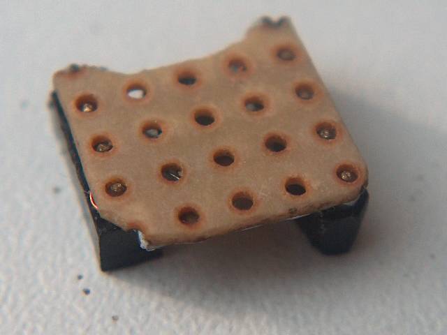
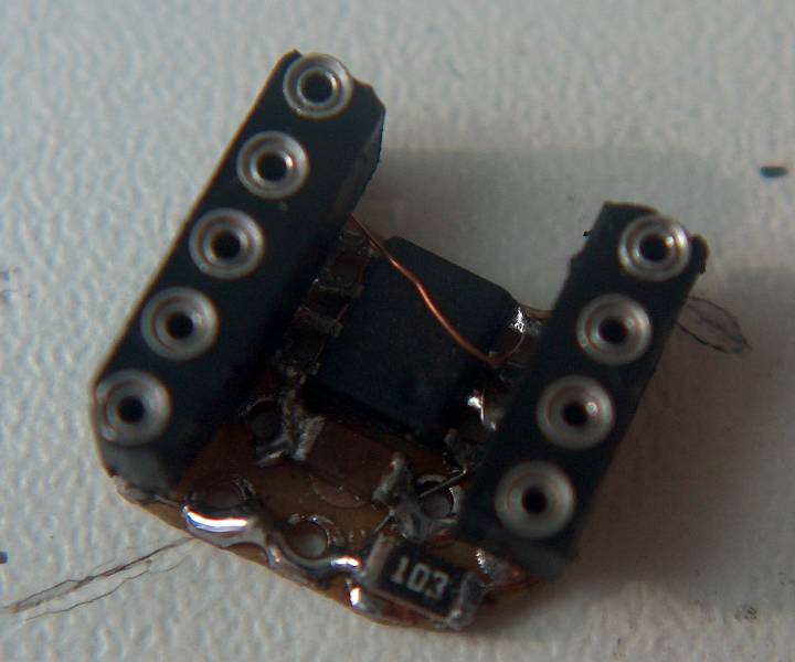
It consists of a small board (slightly smaller than a Flexdrive) with three SMD components (one microcontroller IC) and two connectors. One connector is connected to the laser host and the other can be used to read out the recorded value with an external device.
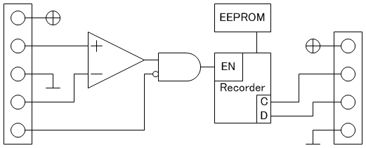
It can record the on-time of both fixed lasers (on-off type) and variable lasers, in which case it starts recording at a certain current threshold. For this, it has two analog inputs and one digital. The analog inputs are compared and if one (the sense) is higher than the other (the threshold) it can start recording. It will also only start recording when the digital input is LOW (inverted input because most hosts have the tailcap switch in the "-" line). If either the digital input is high or the sense input lower than the threshold input, it will store the value and go into power saving mode. For this to work, the recorder should always remain powered. In power saving mode it consumes about 125[ch956]A.
The clock's accuracy is 0.1%, so that's less than 10 seconds error per 24hr.
The value is read back in binary, with one switch and one LED. Every time the switch is pressed, the next bit is shown. Use windows calculator to convert it back to seconds.
There's one glitch; if you remove the supply while it is recording, then it can not store the value and the next time it is recording it starts counting from the previously stored value. This can only be circumvented with additional components that would make it almost twice as large.
Here's a rough functional schematic for the recorder
And some photos.
The next version may have one pin less on the right side because the readout device may not need a "+" line.
Here's how I built it into an MXDL for a violet diode. It literally 'sits' on op of a Flexdrive:


Note that I needed to solder a wire to the "-" pole of the batteries because the recorder should always remain powered.

And here's how I read the recorded value from it. The board with all the stuff you see on the left was actually my development board on which I developed the recorder, but only one switch and the LED are connected through the wire. I will think about making a smarter readout device with a microcontroller and decimal readout. If so, then the next version will still require the fourth pin on the readout connector.

I'm not planning on making these for the masses, so if people want them badly enough, I could consider jointly making them with someone else with experience and who can make PCBs (drlava comes to mind).
I noticed people always try to 'guess' how long they have used their laser, because this value seems somehow important to the well-being of the diode (especially for blu-ray and PHR diodes). This guessing is very difficult, because some people use a laser for 30 seconds duty cycle for 5 minutes per day, others claim to use it 30 minutes per day. To resolve this, I designed a recorder that records how long a laser has been on.
It consists of a small board (slightly smaller than a Flexdrive) with three SMD components (one microcontroller IC) and two connectors. One connector is connected to the laser host and the other can be used to read out the recorded value with an external device.
It can record the on-time of both fixed lasers (on-off type) and variable lasers, in which case it starts recording at a certain current threshold. For this, it has two analog inputs and one digital. The analog inputs are compared and if one (the sense) is higher than the other (the threshold) it can start recording. It will also only start recording when the digital input is LOW (inverted input because most hosts have the tailcap switch in the "-" line). If either the digital input is high or the sense input lower than the threshold input, it will store the value and go into power saving mode. For this to work, the recorder should always remain powered. In power saving mode it consumes about 125[ch956]A.
The clock's accuracy is 0.1%, so that's less than 10 seconds error per 24hr.
The value is read back in binary, with one switch and one LED. Every time the switch is pressed, the next bit is shown. Use windows calculator to convert it back to seconds.
There's one glitch; if you remove the supply while it is recording, then it can not store the value and the next time it is recording it starts counting from the previously stored value. This can only be circumvented with additional components that would make it almost twice as large.
Here's a rough functional schematic for the recorder
And some photos.
The next version may have one pin less on the right side because the readout device may not need a "+" line.
Here's how I built it into an MXDL for a violet diode. It literally 'sits' on op of a Flexdrive:
Note that I needed to solder a wire to the "-" pole of the batteries because the recorder should always remain powered.
And here's how I read the recorded value from it. The board with all the stuff you see on the left was actually my development board on which I developed the recorder, but only one switch and the LED are connected through the wire. I will think about making a smarter readout device with a microcontroller and decimal readout. If so, then the next version will still require the fourth pin on the readout connector.
I'm not planning on making these for the masses, so if people want them badly enough, I could consider jointly making them with someone else with experience and who can make PCBs (drlava comes to mind).


