Welcome to Laser Pointer Forums - discuss green laser pointers, blue laser pointers, and all types of lasers

LPF Donation via Stripe | LPF Donation - Other Methods

Links below open in new window

ArcticMyst Security by Avery

Testing DDl's circuit

Joined
Jul 24, 2007
Messages
2,749
Points
0
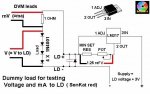
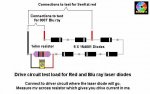
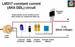
I am about to post a "How To" on testing DDL's circuit before adding the LD, I hope it is all pretty clear and with no errors. Those members who have been there, done that, would you please let me know if you disagree with anything therein.

Regards rog8811
*Edit Circuit layout attached to help with circuit testing

attachment.php
 

Attachments

  • LM317_components01_002.jpg
    LM317_components01_002.jpg
    45.3 KB · Views: 1,913
Last edited:


Joined
Jul 24, 2007
Messages
2,749
Points
0
I have seen so many threads recently posing questions on the expected output of DDL's circuit.

I thought maybe a picture would paint a thousand words :)

Things to check before you start testing

1) Is it wired correctly?

2) Is there enough voltage? (Rule of thumb 6v for reds 9v for blue)

3) If supply is via batteries, are they fresh? (Used ones may sag and effect your measurements)

Now to test it out......

4) Attach the 4 diodes and resistor to where LD will eventually connect. If your reverse diode and capacitor are already connected to your LD you can connect your test assembly to the output from your fixed resistor and the neg of the battery.

5) Turn the pot to maximum resistance (then back off the pot a turn if it is a 25 turn one to ensure the wiper is not right on the end of the resistor track)

6) With your DVM set to volts attach red and black leads as shown at either end of the diodes. Turn on supply, now wind your pot right up to see if the voltage doesn't exceed your required voltage.

7) Turn off the supply, change range on DVM to mv and attach red and black as shown either end of resistor. Turn on supply and the mv reading will be equal to the maximum milliamps that your LD would see, now wind the pot resistance up to check that the reading reduces smoothly down to the lowest mw, which equals the lowest ma your LD will see.

8) You can also connect your DVM, set to volts across the Vout and Vadj pins of the regulator, you should read 1.25v (thanks rckstr)

9) If all seems OK leave the pot at max resistance, disconnect the supply and remove your test assembly.

10) VERY IMPORTANT! If your capacitor is not connected directly to your diode (in other words it is already in the circuit with your regulator) you MUST short out the + and - at the output with a piece of wire to discharge the capacitor. Failure to do so will blow your LD as you connect it up!

The rest of the set up is up to you, the above only checks that the circuit works correctly.


Regards rog8811

attachment.php
 

Attachments

  • DDL_circuit_test01_001.jpg
    DDL_circuit_test01_001.jpg
    46.9 KB · Views: 2,959
Last edited:

rkcstr

0
Joined
Dec 1, 2007
Messages
1,368
Points
0
Oops... realized this isn't the place to post problems, you're just asking if it sounds good....

It does to me... didn't see any errors.

Also may mention to measure the voltage between the Vout and Vadj pin to measure reference voltage to see if your supply is adequate.
 
Joined
Nov 25, 2007
Messages
270
Points
0
omg! thanks you soo much!!! I'm finally figuring this crap out, lol, thanks!

now if only someone would do the same thing using the 7805 regulator!!!! gotta find something to with these things I bought!
 
Joined
Jul 24, 2007
Messages
2,749
Points
0
I set my 7805 circuit up in exactly the same way, excluding the ref v measurment.

The thing to remember is that 7805 must be configured as constant voltage not CC and needs around 7.2v input to drive a blue ray.

I have not tried it for red LD's as I feel there is no point when the LM317 does it so well.

Regards rog8811
[edit]Years later.... test load schematic added[/edit]

attachment.php
 

Attachments

  • test_load01_004.jpg
    test_load01_004.jpg
    41.2 KB · Views: 2,145
Last edited:
Joined
Nov 25, 2007
Messages
270
Points
0
isn't that dummy load designed to best match the red diode?

would I just have to add a few more 1N4001s to make it like a bluray?
 
Joined
Aug 15, 2007
Messages
790
Points
0
member02 said:
isn't that dummy load designed to best match the red diode?

would I just have to add a few more 1N4001s to make it like a bluray?

A good dummy load for a BluRay seems to be 4 green LEDs in a 2x2 parallel-series config.


_______/----LED----LED----\_________
\----LED----LED----/

(`')
I \/ ASCII art
 

chimo

0
Joined
Jun 20, 2007
Messages
650
Points
0
You could also use a 1/4Watt 100 ohm resistor for a BluRay dummy load. It is fairly close to the dynamic resistance of the BluRay when running at around 40-50mA. You can also calculate the current in your head by measuring the voltage and dividing by 100.
 

Cxrazy

0
Joined
Aug 15, 2007
Messages
179
Points
0
This helped me.

A lot.

I'm rebuilding mine, and well see how it turns out. :cool:
 
Joined
Jul 24, 2007
Messages
2,749
Points
0
Thanks for the additional input guys, as long as the good stuff is located on page one it may remain a useful thread.

To those for whom this is helpful with their projects, I am glad to have been of assistance. ;)


Regards rog8811
 

jayrob

0
Joined
Sep 21, 2007
Messages
9,862
Points
113
rog8811 said:
Thanks for the additional input guys, as long as the good stuff is located on page one it may remain a useful thread.

To those for whom this is helpful with their projects, I am glad to have been of assistance. ;)


Regards rog8811

Good stuff Rog! You know I will be marking this thread. Thanks for doing this...
Jay
 
Joined
Nov 28, 2007
Messages
303
Points
0
rog8811 said:
Thanks for the additional input guys, as long as the good stuff is located on page one it may remain a useful thread.

To those for whom this is helpful with their projects, I am glad to have been of assistance. ;)


Regards rog8811

Good info Rog8811. I wish I had found this info before I spent a bunch of time chasing my tail. Luckily you and some others responded in a thread I made.
 

Daedal

0
Joined
May 23, 2007
Messages
2,277
Points
0
Excellent! :D

Yet another great write-up by Rog :)

Hopefully once I get away from all the GB's (soon), I'll be contributing some more as well...

--DDL
 

ice

0
Joined
Nov 23, 2007
Messages
13
Points
0
hey guys, any ideas how to discharge end capacitor after power - off [smiley=huh.gif] ? I mean placing a discharging resistor across cap, or to use dual switch for power, AND shorting cap :). would that work? . I blew my LD by forgetting to discharge that damn cap :(
 
Joined
Nov 24, 2007
Messages
321
Points
16
???... The cap SHOULD discharge through the diode when you power off. I've never had a problem with cap discharge except when I accidentally unplugged & replugged the diode into it's socket WHILE the circuit was energized...???

Dave
 

ice

0
Joined
Nov 23, 2007
Messages
13
Points
0
xanatos said:
???... The cap SHOULD discharge through the diode when you power off. I've never had a problem with cap discharge except when I accidentally unplugged & replugged the diode into it's socket WHILE the circuit was energized...???

Dave

yeah, but Im thinking of another way to discharge cap. I powered on/off circuit without LD, and cap held charge which killed LD after I connected it.


Top