Welcome to Laser Pointer Forums - discuss green laser pointers, blue laser pointers, and all types of lasers

LPF Donation via Stripe | LPF Donation - Other Methods

Links below open in new window

ArcticMyst Security by Avery

Testing DDL Circuit with multimeter

chido

0
Joined
Dec 4, 2007
Messages
1,918
Points
0
Ok, in the diagram it looks like the + and - wires coming from the driver are connected together??? Also, you're measuring from the - wire, it's supposed to be the + wire. And where's the 1 ohm resistor???

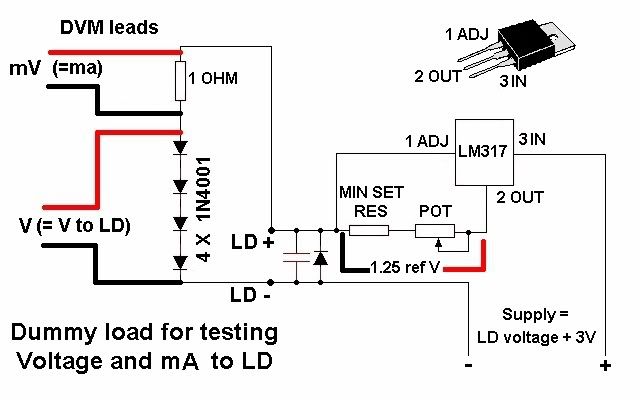
All you have to do is measure like in rog's schematic. Replace the silicon diodes with the actual LD of course and measure the mV. When using the 1 ohm resistor 1mV = 1mA.

clip_image001.jpg


viroy

0
Joined
Mar 20, 2008
Messages
126
Points
0
I had the actual laser diode connected when testing.
The + and - are not connected.
 

viroy

0
Joined
Mar 20, 2008
Messages
126
Points
0
No, I just connected the DDL circuit directly to the diode. Im reading with the DMM right off the leads to the diode after the DDL circuit.
 

chido

0
Joined
Dec 4, 2007
Messages
1,918
Points
0
See, that's what you're doing wrong, use a 1 ohm resistor between the positive leg of the diode and the positive wire coming from the driver. Then set your DMM to the 2000mV setting and place your probes like in rog's schematic.
 

viroy

0
Joined
Mar 20, 2008
Messages
126
Points
0
Darn I dont have any 1 ohm resistors here, ill have to get them.
Last time I remember looking at them at radio shack, they look like a large ceramic block.
any particular kind i should get? id like to get it from radio shack tomorrow.
 

chido

0
Joined
Dec 4, 2007
Messages
1,918
Points
0
As far as I know, any 1 ohm resistor should work.
You don't necessarily have to use a 1 ohm, you could use other values but you would have to divide the measurement by the resistor's value. For example, if you use a 1 ohm resistor, 1mV = 1mA. But if you use a 10 ohm resistor, then 10mV = 1mA. If you turn the pot all the way down, the resistors in your driver will limit the current to 250mA, if you use a 10 ohm instead of a 1 ohm to measure, then you would see 2.5v on your multimeter.
 

viroy

0
Joined
Mar 20, 2008
Messages
126
Points
0
Ok 10ohm resistors I do have.
So I should put the 10ohm resistor on the + side between the DDL circuit and the + diode lead.
Then test with the DMM, placing the + lead before the resistor and the - after the resistor, set to 2000m.
Then take that reading and divide by 10 = ma

Correct?
 

viroy

0
Joined
Mar 20, 2008
Messages
126
Points
0
Ok I just connected everything as stated above...
I get a reading of 1986

So 1986/10 = 198.6ma?
 

chido

0
Joined
Dec 4, 2007
Messages
1,918
Points
0
Did it show up in the meter as 1.986v? If it did then that's correct.
Try to get a 1 ohm resistor though, it makes measurements a lot easier. The 10 ohm resistor will let you measure accurately up to 200mA. If you get past 200mA, say 220mA it would display on your meter as 2.200, but since the 2000mV setting is only good up to 2v, anything above 200mA will display as a 1.
You could try putting it in the 20v setting. But your results will display 0.00, instead of 0.000 with the 2000mV setting. So you'd only be able to measure increments of 10mA.
 

viroy

0
Joined
Mar 20, 2008
Messages
126
Points
0
Ok, I will get a 1 ohm resistor for future testing.
Im comfortable with this ruuning at 200ma unless you think that can go up to 300.
but if 250 is its max, I dont wanna push it.

FYI - I have a 20x burner on the way, that driver im going to use 3.3 ohms so I can reach a comfortable 350ma. From what I understand, the 20x burners go up to 350?
 

chido

0
Joined
Dec 4, 2007
Messages
1,918
Points
0
200mA should be fine, it should be putting out in the neighborhood of 130mW.
The sweet spot for 20x long open can diodes is 420mA, at that current they put out around 240mW.
BTW, what drive did you order?
 

viroy

0
Joined
Mar 20, 2008
Messages
126
Points
0
oh wow only 130mw? now is it these 16x diodes are supposed to put out up to 250mw, or take up to 250ma?

The 20x is a Sony ad-7190a:
newegg.com/Product/Product.aspx?Item=N82E16827118003
 

chido

0
Joined
Dec 4, 2007
Messages
1,918
Points
0
A 16x diode can take more than 250mA but it might not live too long. It depends on the diode. For example, SenKat's old diodes gave great results at 250mA and they were 16x. Now he's selling new ones which can handle much more current. Hemlock mike drove one for 14 hours at 400mA with no degradation in power, it was putting out 240mW.
Since I don't know how much current yours can handle, I don't recommend you go above 250mA. Here's a graph Hemlock Mike made a long time ago of the old 16x diodes SenKat used to sell, he compared one to an open can diode. The 16x diode curve is the one labeled "Sony GB."

clip_image004.jpg


That DVD is a great choice.
 

viroy

0
Joined
Mar 20, 2008
Messages
126
Points
0
wow thats cool.
So from what I see, I should add another 10ohm resistor to this circuit for the 16x diode, the POT maxes out at like 220ma and it sounds like I might be able to go up quite a bit.
I do have yet 1 more 16x diode, so im not too worried but would like to save it.
I also have a 12x diode, what do you think that can take?
 

chido

0
Joined
Dec 4, 2007
Messages
1,918
Points
0
I had a SenKat diode from the "bad batch" apparently those weren't 16x but 12x. I drove it at 150mA only and it died after 30 minutes of total run time. :(


Top