Welcome to Laser Pointer Forums - discuss green laser pointers, blue laser pointers, and all types of lasers

LPF Donation via Stripe | LPF Donation - Other Methods

Links below open in new window

ArcticMyst Security by Avery

Simple Adjustable Laser driver (V. 2) It Works!!!

Zom-B

0
Joined
Mar 25, 2008
Messages
895
Points
28
Re: Simple Adjustable Laser driver (V. 2) It Works

Yes milliWatt (not Mega watt :p), they were modules I built for sale a while ago.

With multilayer, do you refer to my driver or that last photo?


Joined
Sep 8, 2008
Messages
182
Points
0
Eureka!

Hello All,

Received my PHR-803T yesterday. It's in the host and working great!!! The only differences between the circuit I built and the schematic are that I used an IRL-520 logic-level mosfet and instead of a 9k resistor, I used an 8.3k (what I had on hand...) Anyway, I now have a 405nm laser running off of 6v. I'm working on a p-channel version for case-cathode diodes. So stay tuned.

I'll post pics once I'm off of work. I took some shots last night. But the beam is harder to photograph than the reds. I haven't quite figured it out yet...

cheers,
kernelpanic

p.s. I'm running my diode at 130mA. the driver is very stable. Using 1% resistors current doesn't vary by more than ~1%. So far I've got over an hour on the diode, 30 seconds at a time. ;)
 
Joined
Sep 8, 2008
Messages
182
Points
0
Re: Simple Adjustable Laser driver (V. 2) It Works

hello all,

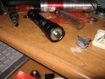
Off woork finally. Here's a pic of the host using this driver. I got the diode from drew. It's the second. (The first I blew adjusting up on my v1 driver as the circuit was non-linear in it's response, hence the op-amp and sense-feedback.)

Also I've drawn up a positive-regulating version with a logic level p-channel for case-cathode diodes. I'll post it once I do the math and figure out the resistor values...

cheers,
kernelpanic
 

Attachments

  • host1_001.jpg
    host1_001.jpg
    117 KB · Views: 458
Joined
Sep 8, 2008
Messages
182
Points
0
Re: Simple Adjustable Laser driver (V. 2) It Works

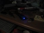
and one of it running...

p.s.- Identify everything on my desk and win a prize! (Alas, not really.)
 

Attachments

  • host2.jpg
    host2.jpg
    67 KB · Views: 390

ArRaY

0
Joined
Jul 18, 2008
Messages
281
Points
0
Re: Simple Adjustable Laser driver (V. 2) It Works

Ok.

There is a great laser,
a screwdriver,
a washer,
misc electronic parts,
a book,
a soldering iron + plastic cover + another soldering iron tip,
some red plastic cover/sheet,
a breadboard,
some cardboard,
some kind of spray,

thats pretty much most of the stuff^^
 
Joined
Sep 8, 2008
Messages
182
Points
0
Re: Simple Adjustable Laser driver (V. 2) It Works

ArRaY said:
Ok.

There is a great laser,
a screwdriver,
a washer,
misc electronic parts,
a book,
a soldering iron + plastic cover + another soldering iron tip,
some red plastic cover/sheet,
a breadboard,
some cardboard,
some kind of spray,

thats pretty much most of the stuff^^

The 'spray' is actually butane for the soldering iron. The 'red plastic cover' is a cd envelope. And you missed the steel epoxy-putty. (It was right there too!) ;)

Thanks for playing the WTF is all that CRAP- home game!

All joking aside, the driver works great. At 130mA my host doean't even get warm and the laser burns! All in all, I'm very happy with my driver. Also, I posted a positive-regulated version in the tutorials section on this thread- http://www.laserpointerforums.com/forums/YaBB.pl?num=1222777857 This circuit is very versatile. One could easily add modulation by feeding the signal to the gate through a bypass capacitor. (My next step, stay tuned...)

cheers,
kernelpanic

p.s.- I received all my digikey surface mount parts yesterday. The surface mount S-220 package will not fit in a module. I need to find a smaller mosfet for that. But it will fit in the dealextreme 4171 sku host with a jayrob heatsink. (I'm building a batch of blu-ray Christmas presents for a few geeks I know.)
 

caleb

0
Joined
Nov 27, 2007
Messages
321
Points
0
Re: Simple Adjustable Laser driver (V. 2) It Works

this driver is awesome.
would you says it is completed? if so i hope i hope to get around to building it. :)
and, and i guess it has to be around 6V, theres no way you can modify or design a new 3-4.5V driver :cool:
sku.46 ::)

thanks man.
 
Joined
Sep 8, 2008
Messages
182
Points
0
Re: Simple Adjustable Laser driver (V. 2) It Works

caleb said:
this driver is awesome.
Thanks.
would you says it is completed? if so i hope i hope to get around to building it. :)
Yes and no. This circuit as-is works well for phr-803t diodes as the cathode is not grouded to the case. For other (read- 650nm) diodes it'll need to use a p-channel mosfet. I'm still sourcing one small enough to fit in the aixiz module and working on the PCB art for a surface-mount version. As for component values, if you're paraniod you can increase the value of the capacitor across the pot. This cap provides hysteresis to the tuning pot and slows turn on. (At 6v the 1 uF provides around 15ms delay.)
and, and i guess it has to be around 6V, theres no way you can modify or design a new 3-4.5V driver :cool:
sku.46 ::)

thanks man.

To use a p-channel and run this off 3v or 4.5v see this thread- http://www.laserpointerforums.com/forums/YaBB.pl?num=1222777857

Just remember this is not a boost circuit. So you want the supply voltage to be slightly larger than the needed diode voltage.

cheers,
kernelpanic
 
Joined
Sep 8, 2008
Messages
182
Points
0
Re: Simple Adjustable Laser driver (V. 2) It Works

Hello All,

At this point I've tweaked the power settings, gone few 2 sets of batteries, then broke down and bought RCR123's.. The current supplied does change depending on supply voltage. But not as much a it would without the diode across the potentiometer. I set it at 140 mA on new cr123's. When I put rechargeable ones in they measured aat 150mA. So if you're using rechargables or plan to, set the driver with them fully charged. If you decide later to use normal lithium CR123's, you only lose 10mA.

cheers,
kernelpanic
 
Joined
Nov 24, 2007
Messages
65
Points
0
Re: Simple Adjustable Laser driver (V. 2) It Works

kernelpanic said:
Hello All,

At this point I've tweaked the power settings, gone few 2 sets of batteries, then broke down and bought RCR123's.. The current supplied does change depending on supply voltage. But not as much a it would without the diode across the potentiometer. I set it at 140 mA on new cr123's. When I put rechargeable ones in they measured aat 150mA. So if you're using rechargables or plan to, set the driver with them fully charged. If you decide later to use normal lithium CR123's, you only lose 10mA.

cheers,
kernelpanic

Do you know why this happens? Would be cool to be able to make it stable regardless of supply voltage. Do you think a more stable voltage reference in place of the diode would help?
 

Zom-B

0
Joined
Mar 25, 2008
Messages
895
Points
28
Re: Simple Adjustable Laser driver (V. 2) It Works

Hi again

I've finally found the time to try my own circuit (or rather found the need :)). I used my BUZ11 and it works. One important thing to note is that the resistor between the opamp and the MOSFET is REQUIRED. (R11 in my schematic) Without it, it oscillated like hell at a frequency between 150 and 300kHz. I initially took a resistor of 10K Ohm, which works well, so I haven't tried the 22K in the schematic (which was guesstimated anyway). For the input divider circuit, I took for X2 a 5K multi turn potmeter, and I calculated the other ones for a programmable range of 50mA-500mA. I derived the reference voltage directly from 5V, not from the Zener as shown in the schematic. The result is R12=56 Ohm 1% and R8=499 Ohm 1% (from E96 sequence). For other values of X2, scale these values accordingly.
My potmeter X1 is an aircraft grade 10-turn potmeter of 950 Ohm 2%, so I also placed an opamp between X1 and X2 wired as a voltage follower, to get rid of impedance differences. (I used LM324 instead of CA3240).
 
Joined
Sep 8, 2008
Messages
182
Points
0
Re: Simple Adjustable Laser driver (V. 2) It Works

positron said:
Do you know why this happens? Would be cool to be able to make it stable regardless of supply voltage. Do you think a more stable voltage reference in place of the diode would help?

You are correct. The voltage drop across the diode increases with current. Using a zener voltage reference would correct this...

cheers,
kernelpanic

p.s.- Zom-B, Which resistor are you referring to? You say R11, but then you say 22k in the schematic and R10 is 22k while R11 is 1k...
(I haven't had any problems with oscillation in my circuit. Did you try it without C8?)
 

Zom-B

0
Joined
Mar 25, 2008
Messages
895
Points
28
Re: Simple Adjustable Laser driver (V. 2) It Works

Yes, my bad, I meant R10. R11 is 10K too on my breadboard, maybe that confused me.

C8 can only prevent oscillations, though not that low in frequency (unless my breadboard has parasitic resistances between columns). Either way, WITH the resistor is always safe, and it's cheaper than blown-up diodes.
 
Joined
Jan 7, 2007
Messages
6,309
Points
83
Re: Simple Adjustable Laser driver (V. 2) It Works

Am I doing something wrong?? The pictures are HUGE and I can't see much of it without groping around.

Mike
 
Joined
Sep 8, 2008
Messages
182
Points
0
Re: Simple Adjustable Laser driver (V. 2) It Works

Zom-B said:
Yes, my bad, I meant R10. R11 is 10K too on my breadboard, maybe that confused me.

C8 can only prevent oscillations, though not that low in frequency (unless my breadboard has parasitic resistances between columns). Either way, WITH the resistor is always safe, and it's cheaper than blown-up diodes.

The resistor will work. But I think that C8 could cause oscillation. I totally understand what you're thinking. (op-amp filter) But that's for signals. A filter by definition will block some frequencies but pass others. Our 'signal' is the feedback from the sense resistor running into the inverting input of the op-amp. Ideally this will be no signal(i.e. a flat line). Putting a capacitor there feeds signal back into the op-amp. But it takes time for the load to adjust. So you get oscillation. Driving a resistive load this may have created an RC oscillator. (I'm just guessing here. But it's an educated guess...) You might try running that cap to ground instead of using feedback and see what happens.

cheers,
kernelpanic


p.s. Mike- All but one of my pics are scaled down. But people do post some big pictures on this forum... ;)
 

Zom-B

0
Joined
Mar 25, 2008
Messages
895
Points
28
Re: Simple Adjustable Laser driver (V. 2) It Works

I've tried with the cap like you suggested and it creates hella big ringing pulses (>150% of signal) at each rising edge.

I tried to play with the values of both resistors and the cap between the output and input and found out that with a certain range of caps and resistors it works better. The cap is now 10nF and the resistors both <1k Ohm. I'm still working on improving the values.


Top