Welcome to Laser Pointer Forums - discuss green laser pointers, blue laser pointers, and all types of lasers

LPF Donation via Stripe | LPF Donation - Other Methods

Links below open in new window

ArcticMyst Security by Avery

Schematic help - trying to build driver

Joined
Jan 20, 2008
Messages
1,724
Points
0
Having burnt out my last rkcstr driver and after waiting some 8 months for fusiondrives to arrive, I've been growing slowly more impatient, staring at these 803t diodes I can't play with...

After tearing apart all my spare electronics I haven't been able to find any LM317's, though a number of DVD burners I have contain 3 or more APL1117's...

I brought up this regulator before, and it seems they would be good to make drivers out of, in fact that's what the FusionDrives use... I would simply copy the schematics for the fusiondrive, but I can't seem to find any of the 1.2v voltage reference chips they use.

phenol posted this handy schematic for a potential driver design:
l1117.JPG

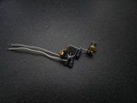
and I tried to build it using whatever parts I could find...

Not having access to any tantalum capacitors, and not being able to find ceramic capacitors in my junk bin that were more than 0.1uf, I used electrolytics...

I looked over the schematic a few times, and looked over what I built... and it seems I put it together correctly, though in place of the resistor I used a 1k pot and a 2ohm resistor, thinking I could play around with the resistance to see what works...

It doesn't seem to be regulating current since it fluctuates between 350-400mA as it heats up, and regardless of what I set the pot to it doesn't seem to make any difference.

I tried a dummy load of 5 diodes in series and within 10 seconds it had melted them. (at around 390mA)

Any idea what I'm doing wrong?
 

Attachments

  • lobsterdrive.JPG
    lobsterdrive.JPG
    39.8 KB · Views: 278


Joined
Jan 20, 2008
Messages
1,724
Points
0
Here's the obverse side.

I don't know that these pics will help anyone, you can't really make anything out, but from what I can tell it's connected according to phenol's schematic.

Does anyone know what sort of resistance range this should use for a sane current range for a laser?
 

Attachments

  • lobsterdrive2.JPG
    lobsterdrive2.JPG
    37.4 KB · Views: 313

rkcstr

0
Joined
Dec 1, 2007
Messages
1,368
Points
0
Those capacitors stabilize the regulation. I've run into problems with my driver and stability in the past, which seems common with the low-drop-out equivalents of the LM317, such as the 1117 and the one I use MC33269.

The electrolytic on the output may be OK, but the input is probably not going to work well with an electrolytic. The ouput bypass cap (C2) may or may not be good with the electrolytic. Also electrolytic caps tend to change a lot with temp, which may be influencing the regulation as well. Tantalum caps shouldn't be hard to find, just search google for some pics of some thru-hole types and see if you can find any that look like them. Also, the input cap (C1) may need to be ceramic or low ESR tantalum as well.

And, what kind of diodes were you using that you melted them :eek:
 
Joined
Jan 20, 2008
Messages
1,724
Points
0
rkcstr said:
...And, what kind of diodes were you using that you melted them :eek:
They're visible on the far right side of the last picture I posted... I got them at radio shack and completely forget what they are.. I'm not sure the packaging even said, I think it may have just been labeled "silicon rectifiers" or something. The writing on them is illegible.
The diodes themselves didn't actually melt, I suspect they're made of glass. Just the solder bridges between them melted.

As I understand it, ceramic and tantalum caps are labeled NNX where NN would be the first two significant digits and X would be the multiplier in picofarads. I can't seem to find any "dipped" capacitors with an X value higher than 4, which correct me if I'm wrong, would put them in the 0.1uf range...
 

phenol

0
Joined
Oct 30, 2007
Messages
533
Points
18
the diodes ure using look like small-signal switching diodes, such as 1N4148 or similar, which are utterly incapable of handling beefy currents />200mA/ for a long time without overheating. Use the 1N4000 series instead.
Moreover, in your pics it looks as if the load is connected to the tab/heatsink/ of the regulator, which is its OUTPUT pin in fact. If such is the case, your circuit will not work as a current source. The load /dummy load/ is connected between ADJ pin and ground (- of battery).
Also, what is the lettering on the regulator chip you're using?
 
Joined
Jan 20, 2008
Messages
1,724
Points
0
phenol said:
...
Moreover, in your pics it looks as if the load is connected to the tab/heatsink/ of the regulator, which is its OUTPUT pin in fact.
...

Oh wow.. that would probably do it! Always remember to check the datasheet! ::)

Also, what is the lettering on the regulator chip you're using?
APL1117
GG595

As for the load, I was also using a red laser that I'd previously led-ified... seems I have a few of those :-[

Thanks for the advice, I'll try correcting the out and adj pins... you don't suppose that would have killed this one do you?
 

phenol

0
Joined
Oct 30, 2007
Messages
533
Points
18
Thanks for the advice, I'll try correcting the out and adj pins... you don't suppose that would have killed this one do you?

It is probably intact. If you have doubts of having reversed the polarity of the battery even for just a second, though, I would suggest you throw that one away and put a new regulator in its place.
 
Joined
Jan 20, 2008
Messages
1,724
Points
0
YAY!

So I got it working... I attached the out and adj pins correctly, used different capacitors and made a dummy load out of some beefier diodes...

lobsterdrive10qa3.jpg

lobsterdrive10actionci8.jpg


The pot, being 10k, was really touchy.. so I ended up replacing it with a 10ohm resistor and now it's putting out a solid and steady 125mA.

lobsterdrive11ql9.jpg


Thanks for all your help phenol, I couldn't have done it without you!
 
Joined
Jan 20, 2008
Messages
1,724
Points
0
Oh, and now that I've come this far, maybe I should ask how bad those oscillations you were talking about are...

I don't have access to a scope, is there any way to test that with objects around the house? My multimeter wasn't fluctuating at all, though I don't really know its sample rate...
 
Joined
Jan 20, 2008
Messages
1,724
Points
0
Presenting the Lobsterdrive...

Now, more victory pictures...

lobsterdrive3252234rf6.jpg

Assembled with pushbutton...


lobsterdrive4982356hg4.jpg

The other side...


lobsterdrive5168476za1.jpg

Inserted in plastic holder thing I made


lobsterdrive6455678st5.jpg

And finally into it's new home.
 

phenol

0
Joined
Oct 30, 2007
Messages
533
Points
18
those oscillations are not that bad inasmuch as they are not likely to destroy the load. However, they will decrease the average current supplied to it. They have variable amplitude, depending on the type of caps used /C1 can be 1u ceramic as well/, the current setting, temperature, lead length and what not else...
The oscillations' freq is in the order of MHz, commonplace DMMs dont register them. You need a scope, or an AC coupled frequency counter, or a spectrum analyzer...
 
Joined
Jan 20, 2008
Messages
1,724
Points
0
I was wondering, maybe I could try hooking a speaker up to it... I know I wouldn't be able to hear into the mHz range, but if it's oscillating really bad maybe I'd be able to hear the harmonics of it...

I suppose I should get a scope eventually, but I just can't justify the expense at this point.
 
Joined
Sep 1, 2007
Messages
1,591
Points
0
I used the apl1117 I found mine in a dvd burner (older ones). I like them alot, i have a schematic i can send you if you want to etch your own pcb and make it fit in an aixis module.
 
Joined
Jan 20, 2008
Messages
1,724
Points
0
Cheers toked, I'd really appreciate that... I've still got another dozen or so of these regulators laying around... The burners I found them in have three per, and I have several of these burners still kicking around.

I'm actually going to be buying some copper clad board tomorrow... if I can get my old laser printer working I might even be able to get these etched by tomorrow!

If they're too big to attach to your post you can send them to pseudolobster at gmail dot com


Top