Welcome to Laser Pointer Forums - discuss green laser pointers, blue laser pointers, and all types of lasers

LPF Donation via Stripe | LPF Donation - Other Methods

Links below open in new window

ArcticMyst Security by Avery

Researching a DIY power meter...

Joined
Aug 16, 2007
Messages
241
Points
0
This started over in another thread - I'm reposting it on its own.

woop:
I am actually thinking of rigging up a power curve setup. I don't have a laser power meter, so it will just be using a solar cell or phototransistor and having relative results, unless anyone has any experience calibrating a laser meter with household objects?
I will hook up the current, power and maybe temperature readings to the ADC input of a microcontroller and transmit readings by serial to my PC which will draw a graph in real time thinking this might be of some use!

Zarniwoop:
As it happens I'm experimenting with making a power meter too.
Things to consider - the spectral response of a solar cell varies (fairly linearly) with the light wavelength. You've also got to reduce the light that hits the cell to the point that you don't saturate it with whatever you max mW will be. If you use a lens to spread the beam, it will refract different wavelengths to different degrees, and some lenses will absorb some wavelengths like UV. Then of course there's calibrating it.
I may never get anything useful out of this but it's a fun experiment.

woop:
i was thinking about such things like saturation. i don't think the frequency response is going to matter that much, as i am only going to be using it with reds at the moment.
how are you going to capture the data?
what sort of sensor do commercial meters use? i am thinking of a phototransistor simply because it is easier to implement, i will need a voltage that varies with light intensity from 0-5V for the ADC to be most accurate, so to use a solar cell i will need an amplifier, and that adds another layer of non-linearity
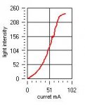
unless i have some way to calibrate it i can pretty much forget about getting accurate mW readings, but i should still get an accurate curve, and the current measurements are easy enough to get accurate.
I could always compare my graph to someone else's and calibrate it that way, assuming a similar diode is being used and the temperatures are the same.
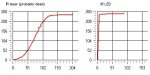


Joined
Aug 16, 2007
Messages
241
Points
0
I don't actually know what kind of sensor the commercial meters use.
Have you seen this guy on eBay?
http://cgi.ebay.com/70mW-Calibrated...ryZ14954QQssPageNameZWDVWQQrdZ1QQcmdZViewItem

I'm just going for a handheld version.
The sleazy version would just output mV to my meter and I'd make a conversion chart. But for phase 2 I'm planning to use a Basic Stamp I've got lying around to do the calibration lookup and output to a display.

If I get all that done maybe I can loan it to somebody with a meter to make a few measurements.

Right now though I'm over-driving the cell even with a rather extreme beam expander lens. I guess I could use several beam-splitters in series or diffraction grating or something.
Looks like more research is needed.
 
Joined
Sep 25, 2007
Messages
209
Points
0
I'm also looking into the design of laser power meters. I have a proper, calibrated LPM-1 on the way so I can calibrate one of my lasers to an exact output, and I'll use that to aid in calibration of a homebrew meter. I'm looking at trying raw silicon photovoltaic panels, phototransistors, and thermal junctions all as materials to test for properties necessary in a proper sensor. My plan is to calibrate this well enough to act as a new probe for my data-logging multimeter.
 

woop

0
Joined
Nov 9, 2007
Messages
342
Points
0
I don't really have time for anything at the moment with yr 12 exams but next week i will be free from school! and then i will experement more with lasers and generating a power curve.
that laser meter on ebay looks really dodgy. i suppose it just uses a phototransistor yeah?
 

woop

0
Joined
Nov 9, 2007
Messages
342
Points
0
ok i got bored of study so i rigged up my laser datalogger.
i just set it up to take a reading whenever the current increased, and i controlled the current using an LM317 circuit.
the current is measured across a 5ohm resistor and the light is measured using a phototransistor with a 1K resistor. its all hooked up to a picaxe (basic stamp clone) which transmits serially to my pc, which collects the data and automatically draws a graph on the fly.

i could calibrate the current well enough, to within a few mA
the Y axis is just a straight reading from a phototransistor, its not calibrated.
this LD is an infrared from a cd burner i think.
 

Attachments

  • lasergraph.JPG
    lasergraph.JPG
    7.6 KB · Views: 206

woop

0
Joined
Nov 9, 2007
Messages
342
Points
0
wow that partucullar laser must be dead. have a look at this graph of a IR led using the same setup.
also on the laser graph, the light doesn't dim when its way overdriven. usually i would expect a laser to die there, but it appears to be already dead.
 

Attachments

  • laserstuff.JPG
    laserstuff.JPG
    18.6 KB · Views: 337

Kenom

0
Joined
May 4, 2007
Messages
5,629
Points
63
stay away from that guys stuff on ebay. he's a joke.
 

woop

0
Joined
Nov 9, 2007
Messages
342
Points
0
hmm. my phototransistor is saturating ::) should have noticed that when the LD sloped off at the same place as the led, and the strange led curve.
its actually really hard to stop it from saturating with such high intenities of IR light
I still think my LD is dead though

why should we say away from the ebay thing? did you get one Kenom?
 
Joined
Aug 16, 2007
Messages
241
Points
0
I guess most of the commercial units use a ND8 or so filter for higher ranges. I think I'd rather just build in a low efficiency beam splitter (like 5:95%) - but then I've got that 95% of 200mW to throw away without melting something. I guess I could expand the waste beam.

One interesting thing I've noticed even with this totally uncalibrated, saturating setup - When my DX20 green isn't visibly lighting up (untill I press harder), I'm still seeing a high output, which must be IR. But since a 5mW will saturate it right now, maybe it's not all that much.

I hadn't really thought about output to a PC but now that you bring it up I guess why not also have the Basic Stamp output RS232. Hmm.
 

woop

0
Joined
Nov 9, 2007
Messages
342
Points
0
yeah a live graph is good because it is really easy to see when to back off. or when your setup is obviously saturating
do you think it would be easy to make a 5% beam splitter out of the optics from a dvd/cd drive?
at first i just had the laser pointing directly into the phototransistor...
then i shon the laser on a piece of paper and pointed the phototransistor at the paper. then i did the same, but put paper over the sensor.
i still couldn't get it to stop saturating.
maybe it would be easiest to just have no lense on the laser and mount the sensor a distance away from it so you get a lower percentage of light going into the sensor. this would be impossible to calibrate but it should get a nice curve and at least tell you how hard to drive the diode
 
Joined
Aug 16, 2007
Messages
241
Points
0
That's where I started, was trying to disperse the beam much larger than the sensor. The final focusing lens on all these drives is pretty extreme, but even at that I'm saturating my solar cell 4" away.
I'm experimenting with all the optics I've harvested from various drive modules.
In the Sam's Laser FAQ it suggested using a microscope slide, i.e. a plain piece of glass as a 5% mirror.
Now I'm wondering if I end up with several optical components with critical alignment, if I'd be better off using most of the module from a DVD drive where everything's already held in place.
Downside is that the input diameter is tiny.

Anybody with a real meter: Are they touchy about getting the beam lined up just right for a maximum power reading, or are they at all forgiving?
What size is the aperture?
 

woop

0
Joined
Nov 9, 2007
Messages
342
Points
0
I think some commertial units use a thermocouple device to measure power, so alignment would not be critical

yeah we could just use a piece of glass and align it until it it somewhere around critical angle
 

woop

0
Joined
Nov 9, 2007
Messages
342
Points
0
i just opened up a 32x cd burner. and the laser diode had 3 pins but the photodiode pin was shorted to ground. it had an external photodiode which was mounted just above the window of the diode so it would have been partially in the uncollimated beam.
I will take a multimeter to it and see if i can reuse it for a power meter.
probably should have left it in the laser assembly
 

Attachments

  • chip.jpg
    chip.jpg
    179.6 KB · Views: 393

woop

0
Joined
Nov 9, 2007
Messages
342
Points
0
damn, i just killed that diode. by running an amp through it :p
i think i should build another layer of protection into my power supply. at the moment it just has a tiny trimpot, and no limiting resistor. so when the trimpot bottoms out the diode dies. I should also get a larger pot
oh well it was only an IR
 

Gazoo

0
Joined
Jun 9, 2007
Messages
3,206
Points
38
I killed an open can that way...they don't like an amp either.
 

chimo

0
Joined
Jun 20, 2007
Messages
650
Points
0
The easiest way is to use a pot and a fixed resistor in series.  Make the fixed resistance value sized to create the maximum current you would like the circuit to run at.  The pot is then used to reduce that current (pot at 0 ohms = max current)


woop said:
damn, i just killed that diode. by running an amp through it :p
i think i should build another layer of protection into my power supply. at the moment it just has a tiny trimpot, and no limiting resistor. so when the trimpot bottoms out the diode dies. I should also get a larger pot
oh well it was only an IR


Top