Welcome to Laser Pointer Forums - discuss green laser pointers, blue laser pointers, and all types of lasers

LPF Donation via Stripe | LPF Donation - Other Methods

Links below open in new window

ArcticMyst Security by Avery

Red DIY DVD laser burner.

Kenom

0
Joined
May 4, 2007
Messages
5,629
Points
63
it's not that important to use thermal epoxy. As a matter of fact in my latest builds I'm not using it at all.


kdubbz

0
Joined
Aug 15, 2007
Messages
51
Points
0
just a question here, going to be getting my diodes here soon, and I was wondering kenom have you started adding capacitors to your later dorcy jr burners? If so, which cap would best suit these?
 

Kenom

0
Joined
May 4, 2007
Messages
5,629
Points
63
it is pretty important to start adding things to this circuit so that your not blowing out diodes. As someone mentioned before, you should place the cap (27 - 33uF) on the diode leads, also to be really safe put a 1N4001 across the diode in reverse. That is from Robk. it's not a bad idea. I'm going to start at minimum using the cap.
 

Skram0

0
Joined
Aug 25, 2007
Messages
280
Points
0
For the 1N4001 diode, he probably meant something like this. It's in reverse as to protect the circuit from reversed polarity. Positive current on the top will not pass through it to negative and go to the LD load. But if the circuit polarity was reversed (positive on the bottom), current would flow through the diode (to the top) as a load and not through the LD in reverse protecting it from damaging reverse current.
 

Attachments

  • diode01_001.jpg
    diode01_001.jpg
    10.6 KB · Views: 244
Joined
Aug 17, 2007
Messages
238
Points
0
Hey Guys:
Maybe I missed it among all of this info but what is the safest desired current to feed the Kenom Torch LD if we're working with a 5 volt source and a 2.7 voltage drop across the LD. Is a range of between 150 to 200 ma OK AND will it produce a good burner? I'm trying to find the happy median between LD longevity and output power. Thanks.
 

Kenom

0
Joined
May 4, 2007
Messages
5,629
Points
63
Your looking at the sweet spot about 200-250ma. At that output your going to be gettting a burner and not throwing yoru diode down the tubes. As far as how much the circuit inside the dorcy is concerned your looking at 350-400ma so it's defenitly needing regulation above and beyond what's normally inside the dorcy. I'm contemplating taking the existing driver out and putting in the driver here
http://dealextreme.com/details.dx/sku.3160
 

Kenom

0
Joined
May 4, 2007
Messages
5,629
Points
63
the one problem I am having with this particular circuit is it requires minimum of 3.6v in and a cr123 battery or 2 AA's or 2AAA's don't equal enough to drive this. Not to mention I'm concerned that 350ma is a bit much for the GB diodes. but since there is sooooo much room on this circuit it should be relatively easy to solder some new stuff on to it. Like a resistor or two.
 

Gazoo

0
Joined
Jun 9, 2007
Messages
3,206
Points
38
I noticed that too, but it would run fine on three NIMH rechargeable batteries, or alkalines.. or one RCR123 battery.

One would be relatively safe using a protected rechargeable lithium. So if they do keep regulation within 10%, they might be worth a try.

I think the Dorcy Metal Gear might be the perfect candidate for these using NIMH batteries.

It is hard to tell from the pictures, but it does seem to me on most of these there is already a capacitor across the output. So as you said all you would need to add is an additional resistor. It's a shame they don't sell these in fewer quantities so we could test them.
 
Joined
Aug 17, 2007
Messages
238
Points
0
Kenom said:
Your looking at the sweet spot about 200-250ma. At that output your going to be gettting a burner and not throwing yoru diode down the tubes. As far as how much the circuit inside the dorcy is concerned your looking at 350-400ma so it's defenitly needing regulation above and beyond what's normally inside the dorcy. I'm contemplating taking the existing driver out and putting in the driver here
http://dealextreme.com/details.dx/sku.3160
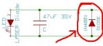
I was just going to limit the current with a resistor in series with the LD, Ken. Then, parallel the 47uf cap. I did not do this the first time, not even the cap when the LD blew.
 

Kenom

0
Joined
May 4, 2007
Messages
5,629
Points
63
I've got one if ya wanna see better pictures. bah. I'll just post a picture.


Kenom

0
Joined
May 4, 2007
Messages
5,629
Points
63
oh and for anyone interested here is a picture of the original dorcy circuit.


Gazoo

0
Joined
Jun 9, 2007
Messages
3,206
Points
38
Wow...so all the board consists of is the 7135 and a diode. But there is a lot of room on it...looks like a capacitor is needed in addition to a resistor.
 

Kenom

0
Joined
May 4, 2007
Messages
5,629
Points
63
ok gazoo, take a look at the two pictures and post on the board on the picture where one could solder the resistors and capacitor and then on the original dorcy circuit take a look and see if it can be modified to be variable like daedals circuit.
 

Gazoo

0
Joined
Jun 9, 2007
Messages
3,206
Points
38
Comparing to the diagram on the data sheet the pinouts of the regulator are as follows.

Looking at it in your picture:

Left Leg = Vdd Or positive in
Middle leg = Ground
Right Leg = Voltage Out

If you follow the traces on the board you will be OK.

Looking at the data sheet again, this thing can run on a minimum of 2.7 volts. Current will be dependent on input voltage. So it would be safe to test it out using a CR123 battery and check the current going to the laser diode. The diode on the circuit board I assume is for polarity protection. All you might need to add is a capacitor across the laser diode.

Regarding the Dorcy circuit, I am sorry but honestly I am not familiar with it so I would have no idea where to begin. :'(


Top