- Joined
- Feb 25, 2010
- Messages
- 1,643
- Points
- 113
Gentlemen, a new Combiner Class Laser hand held...
THE "Purple pHaze" Combiner Class Laser Illuminator
Here we go again....it has been awhile...but, I have been busy on another Combiner Class " Hand held " build project.....Better grab a Beer......this is a long read:beer::beer::beer:
The Concept
The Purple pHaze will be a combiner class, dual-diode unit which combines a Nichia 7875 Blue Laser (9mm) Diode @ 445nm and a Oclaro 63193 Red Laser Diode @ 640nm . The design will call for the raw CW output power of 7875 (Blue) to be nominal 2W and the 63193 (Red) to be 1W.
The goal is to realize the maximum luminosity of a perceived beam propagation in the secondary colour of Violet/Purple in the visible light spectrum.
The response of the human eye to various wavelength is documented with the attached " Wavelength Response Document" pic. Our eye is constructed such that the photons seen ( reflected ) from the 445 nm beam (Blue) have an apparent luminosity factor of 0 .0430 and the photons seen (reflected) from the 640 nm beam (Red) have an apparent luminosity factor of 0.175 . These response numbers reference the apparent luminosity of the Blue and Red colors.
See the link Spectral sensitivity - Wikipedia, the free encyclopedia .
Also see the attached "Human Eye response to Wavelength" chart. These physiological responses are well documented. As the attached Human Eye response to Wavelength chart shows, our eyes have a peak response at the 555nm line ( Green-Yellow)....Red not near as much, Blue even less than Red and Purple much, much less than Blue.
In a mixed/combined beam propagation, as in with a mixed Blue and Red, both beams are present in the single beam path. Our eyes are receiving the air-particle reflections from both Blue and Red. Our sensitivity to the Red and Blue color is constant, even though the beams are in the exact same path/space and are mixed.
Our brain, however, will mix the two colors to result with a perception of Violet/Purple color...but our eyes still receive the emission lines of 445nm and 640nm. With those Blue and Red nm/emission lines... comes a much higher apparent luminosity than that of the typical Violet/Purple line of 410nm.
In calculating the apparent luminosity of the mixing of the Nichia 7875 Blue LD @ 445nm and an Oclaro 63193 Red LD @ 640nm, a weighted average calculation is done. See attached chart/pic "Response Luminosity Red_Blue weighted average 2".
The results of the simple weighted average math calculation are equal to an apparent luminosity factor of 0.08747. This apparent luminosity factor is much, much greater than that of the single 410nm Violet/Purple color !!!
The take away is that a mixed beam propagation will appear much brighter....by a factor of 11.82 !! Again, reference the "Wavelength Response Document" pic. The 410nm line (Violet/Purple) has an apparent luminosity factor of 0.0074. So... 11.82 x 0.0074 = 0.08747
If my premise is correct,( I hope it is !!! ) then, the luminosity of the "Purple pHaze" design will be equal to a diode or diode combination of 3W x 11.82 or.... 35.46 W of raw output CW power at the 410nm line ( Violet/Purple) to generate the same apparent luminosity of the Purple PHaze design.
So, if we want a Violet/Purple beam, which appears to have great brightness/luminosity...then the logical choice is to use a combiner design which unites a Blue and Red beam and gives a very bright looking Violet/Purple beam indeed.
The Build
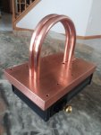
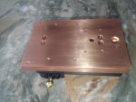
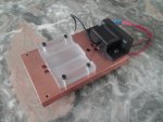
This build is based on the non-traditional format of a rectangular/box design. I started with a 16mm thick, 2 Kilo (5.35 lbs) slab of solid Copper as the heat sink/optical platform. Dimensions of the Copper slab were machined down to 103mm wide by 149mm long. The thickness was left at 16mm thick.
I opted for this because Copper is the best at absorbing heat ( Aluminum is best for dissipation to the atmosphere) and a solid slab - passive design is a simple approach. This design uses no fans ( noise), uses no power as would active TE.....but... is a bitch to drill/tap and surly is no lite weight !!...but...again....sucks up heat like a sponge !!!
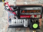
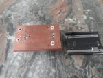
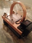
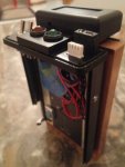
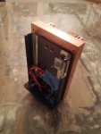
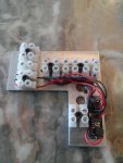
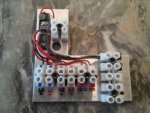
See the attached drawings. As illustrated, the battery, drivers, switches and wiring are located in a extruded Aluminum component box positioned under the Copper slab. Just enough room to get everything in !!! The top surface of the Copper slab serves as the platform elevation for the Laser diodes, corrective optics, steering mirror and combining Dichroic filter/mirror. This multi-level approach makes most use of the unit footprint.
At the heart of the optics is a Dichroic mirror/filter which is used to combine the Red beam with the Blue beam. This mirror/filter is a small rectangular section of glass with special coatings. In this Dichroic, the Red beam passes thru the filter with about 99 % of the light passing thru ( Transmissivity) ...and the Blue beam reflects off the opposite side with about 98% of the light bouncing off at a 90 degree angle ( Reflectivity). This is how the two (2) beams are combined and then have a joined / shared axis. This optical technique can only be used when there is a difference between the two (2) wavelengths one wants to combine.
I also opted to correct each beam with a pair of cylindrical lenses. This arrangement is called a "Cylinderical Telescope set". Both these diodes benefit from corrective optics ! The Red demands it and the Blue is much tighter with it.
You may ask...why not combine the beams first....and then use just one (1) set of cylindrical lenses ?? Well....that would be nice....but unfortunately, the cylindrical set for Blue demands a slightly different distance between the cylindrical lenses than does the Red to achieve the minimal divergence for each color. So... I really needed two (2) separate pair of Cylinderical Telescope sets.
The collimation lenses are; The LSP - 2mm EFL Aspherical for the Red and the G2 for the Blue. The drivers are adjustable X-drives from Lazereer and are set at 1.15 A for the Red and 2.2 A for the Blue.
For unit power, I decided upon a Turnigy 2S LiPo hardcase 7.4 VDC 4000 mah battery. Fortunately, Turnigy makes a small compact unit with outside dimensions of 95mm x 46mm x 25mm. This size fit perfect inside my Aluminum component box. The Battery resides within the component box.
I may leave it in place for the recharge operation. Maybe !!! Not sure yet....Or....it may be a safer option to remove the battery for a recharge.
The design is set up to charge " In Situ" or remove to charge. The suggested protocol for recharging a LiPo battery pac is to remove it from any containment, follow the manufacture rate of charge recommendations exactly and never recharge without continuous supervision during the entire charge procedure. I use an advanced "Smart Charger " which monitors the LiPo cell balance and cell voltage as to optimize the unit charge.
The Purple pHaze unit incorporates a compact digital VDC meter to monitor the voltage drop on the LiPo cell pack. Such a read-out is strongly recommended when management of LiPo cell health/status is a concern. As an added feature I decided that it would be nice to monitor the Copper slab temp via a probe located very close to the LD mounts. While this temp. metric is lagging behind real-time LD core temp...all is relative and I am just curious as to what the Copper heatsink will show with various run times. For this purpose, I incorporated an LCD backlit display that shows the temp. in both analog and digital display. Colorful and informative.
There are four (4) Switches;
S1- I/O for power from the driver to the Blue Laser diode
S2- I/O for power from the driver to the Red Laser diode
S3- I/O for power to the VDC Temp. monitor
S4- The main switch with three(3) possible selections - Off/Laser Armed/Laser On
The reason behind the selection of this specific Main switch is one of safety. This switch is a toggle style unit with three (3) possible positions.
1) With the toggle fully to the Left orientation, NO power is available for both Laser drivers/diodes. This is called the "OFF" position.
2) With the toggle in the centre position, we still have NO power available to the Laser drivers/diodes...but now the Red LED indicator light is flashing Red. This is called the "Arm" position.
3) With the toggle fully to the Right orientation, Power is applied to both Laser drivers. The Green LED indicator light is now solid on and the Red LED indicator light continues to be on. This is called the "On" position.
For both Laser diodes to fire, The main switch must be in the " On" position and both switches S1 and S2 must be in the on position. This is how I choose to set this unit up.
I wanted the option to have Red, Blue or a Purple beam !! It may be said that there are too many switches. Maybe. Maybe not. I tried to anticipate unit operations and what would be good to incorporate.
This build started in October of 2014. A long time...but...a great deal of planning, designing, machining and hoping the build would ...first work and....secondly verify the concept. Fortunately, the area needed for the upper optical platform elevation matched closely the area needed for the lower component box.
I consider this entire build...experimental ! This concept could possibly be reduced in size or could be incorporated in a standard round / tube geometry . But for now....I am well pleased with the outcome !!
Progress to Date
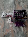
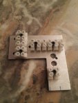
All components are gathered. See pics. Component assembly to begin shortly. A " Pre-assembly" was done ( See Ortho View pic ). Ready to do the wiring and attach the optics to their mounts. Wish me luck going into the concept verification phase !!! Pass the popcorn and stay tuned for the home stretch.
My goal is a whole lota Purple beauty !!
We will see !!!
CDBEAM
Attachments
-
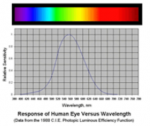 Human Eye response to Wavelength.png70.6 KB · Views: 208
 -
 Response lumonisity Red_Blue weighted average mod 2.png10.7 KB · Views: 205
 -
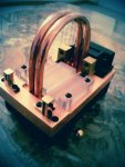 Purple pHaze Ortho view 1.jpg16.1 KB · Views: 313
 -
 Purple Phase V777 ZC.JPG46 KB · Views: 282
 -
 Purple PHaze as Built Wire Schematic 8 .JPG43.2 KB · Views: 288
 -
 Purple PHaze Internal 23.JPG51.5 KB · Views: 271
 -
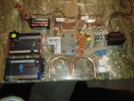 Purple pHaze parts 1.jpg192.8 KB · Views: 310
 -
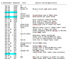 Wavelength Response Document.png23.5 KB · Views: 225
Last edited:


