Welcome to Laser Pointer Forums - discuss green laser pointers, blue laser pointers, and all types of lasers

LPF Donation via Stripe | LPF Donation - Other Methods

Links below open in new window

ArcticMyst Security by Avery

Power curves

Benm

0
Joined
Aug 16, 2007
Messages
7,896
Points
113
I think the same limit also applies with proper passive heatsinking really, at least in terms of operating -current-. The advantage of TEC would be that the diode remains cold, and you'll see more output power at a given current. Also, long-term damange is probably slowed by the lower temperature, but it should have limited effect on the 'poof' type destruction.

You'd need a O'scope to track spikes like that. Few here have a 'scope.

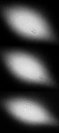
True, i have one and would have used it in case a actually pushed a spike through on purpose. The diode that got the spike seems to have a bit of an artefact in its output now, but power seems to be okay (still burns like it used to mostly).

I think the artifact might be unrelated and caused by something on the output window... not sure what it is or if it can be removed though.


chimo

0
Joined
Jun 20, 2007
Messages
650
Points
0
I have had 2 GB LDs experience just the same thing. Mine are caused by the the coating in the can's window. I removed the can on one and the artifacts disappeared. I would guess the coating is not as robust as the LD output.

Benm said:
The diode that got the spike seems to have a bit of an artefact in its output now, but power seems to be okay (still burns like it used to mostly).

I think the artifact might be unrelated and caused by something on the output window... not sure what it is or if it can be removed though.
 

Benm

0
Joined
Aug 16, 2007
Messages
7,896
Points
113
Did you mechanically damage the coating, or did it just sort of 'blacked' due to the light of the LD blasting it? I'll try to get some pictures later, but i'm not looking forward to removing the can from one of these.
 

chimo

0
Joined
Jun 20, 2007
Messages
650
Points
0
There are some pics in the other thread. It looks like the coating got charred - it should not be mechanical damage.

An easy way to tell if it is on the lens or LD is to put it well out of focus on an wall and rotate the lens (not the module). The blemishes that rotate are on the lens, the stationary ones are at the LD.

Paul

http://www.laserpointerforums.com/forums/YaBB.pl?num=1189268933/7#7

Benm said:
Did you mechanically damage the coating, or did it just sort of 'blacked' due to the light of the LD blasting it? I'll try to get some pictures later, but i'm not looking forward to removing the can from one of these.
 

Benm

0
Joined
Aug 16, 2007
Messages
7,896
Points
113
It turned out to be something on the outside window.. i managed to remove most of it with a qtip... before & after pics below.

Picture is greyscaled to make it more obvious, and its just the diode pointed towards a slightly textured wall without any lens.
 

Attachments

  • beam-artefact.jpg
    beam-artefact.jpg
    233.5 KB · Views: 102
Joined
Jan 7, 2007
Messages
6,309
Points
83
Jes --

I didn't measure temp. I run the TEC at 500 mA -- just enough to keep it cool not cold.

Mike
 
Joined
Sep 16, 2007
Messages
415
Points
0
How do you control current on your Peltier - using something like a LM317, or by voltage?

Mine is too powerful, always blows the fuse on my ATX psu, but gets too cold, too - nothing for "portable".

Any chance of battery-powering the TEC?

PM me if you want, I don't want to hog your thread.
 

Gazoo

0
Joined
Jun 9, 2007
Messages
3,206
Points
38
philguy said:
How do you control current on your Peltier - using something like a LM317, or by voltage?

Mine is too powerful, always blows the fuse on my ATX psu, but gets too cold, too - nothing for "portable".

Any chance of battery-powering the TEC?

PM me if you want, I don't want to hog your thread.

You might want to refer to this thread:

http://www.laserpointerforums.com/forums/YaBB.pl?num=1187495006

You need a small peltier and they do show up on ebay every now and then.

To answer your other question about the LM317, using lithium rechargeables is a very good idea. Daedal's circuit requires a minimum of 6 volts. Any less and the voltage to the diode begins to drop. Just make sure you get a decent brand name battery and a good charger.
 

Daedal

0
Joined
May 23, 2007
Messages
2,277
Points
0
philguy said:
How do you control current on your Peltier - using something like a LM317, or by voltage?

Mine is too powerful, always blows the fuse on my ATX psu, but gets too cold, too - nothing for "portable".

Any chance of battery-powering the TEC?

PM me if you want, I don't want to hog your thread.

The thing about peltiers is they are always looking for enough current to make that voltage worth it. So... the best way to make the peltier something worth wasting the power on, use it at it's designated voltage so that it has the best efficiency and best temperature transfer across the plates. To control the temperature, you need to control the current going into it. Just as you would a diode ;)

In effect... and just as Gazoo did, two LM317's can power your entire setup :)

GL;
DDL
 
Joined
Jan 7, 2007
Messages
6,309
Points
83
I'm using a pair of L200 chips for both. I can run the LD to 600 ma with about 6 volts input. The 500 ma of TEC current is sufficient for now --- -- - - -- - 'till something bigger comes along :D

Mike
 

tomcat

0
Joined
Sep 10, 2007
Messages
352
Points
0
i find that deadals curcit is perfect i have made 3 upto now iv got 120degree 100ohm pots so finetuning is hard... i use a 9v batt with it or a pair of 3v CRs
this graph has enlightend me so thanks mike..

iv got 4 diodes on the way 1 to fix my kenom dorcy jr and 3 for my own mods with 3 different case styles / hosts so i really cant afford to experiment and blow 1.. anyone know the total resistance needed for the lm317 to get 250ma out?? in the daedal curcit i may use a chain of fixed resistors in the final products to hit 250ma
 

Benm

0
Joined
Aug 16, 2007
Messages
7,896
Points
113
It's easily calculated... the LM317 runs 1.25 volts across the resistor, and the resulting current also goes through your diode. This equates to 1.25V/0.25A = 5 ohms. Use 2 10 ohm 0.25W resistors in paralel to be on the safe end of their rating.
 

tomcat

0
Joined
Sep 10, 2007
Messages
352
Points
0
so 5 ohm.. i can get a 5.1ohm metalfilm.. ( 0.6w) thats what im using for the 4ohm with my pot
 

tomcat

0
Joined
Sep 10, 2007
Messages
352
Points
0
so just remove my pot ima gona go on the safe side and use a 6.1.. less power less blown diode..

im making a maglite one what resistance for 2xAA to run at like 230mw (no lm317 of course) im so crap at eletronic maths.... never my strong point. my multimeter says 750mw no load on the pair of AAs..
 

Benm

0
Joined
Aug 16, 2007
Messages
7,896
Points
113
It is impossible to do current regulation from 2 AA's, there is no voltage to work with. At 200 mA, drop over the LD is already 2.8 volts or so, which leaves literally nothing to work with.

You can try a few ohms of resistance, but power output will wildly vary on battery voltage anyways.


Top