

- Joined
- Feb 5, 2008
- Messages
- 6,252
- Points
- 83
OK folks!
This is my sequel to previous thread, in which I went over some basics of making a PCB, along with presenting my new project, temperature regulator for cheap irons.
Well, in previous thread we stopped when we had the components soldered on.
The reason we stopped is because I was missing some parts and had tough luck (running out of soldering wire, breaking only 1mm drilling bit, PCB turned out bad).
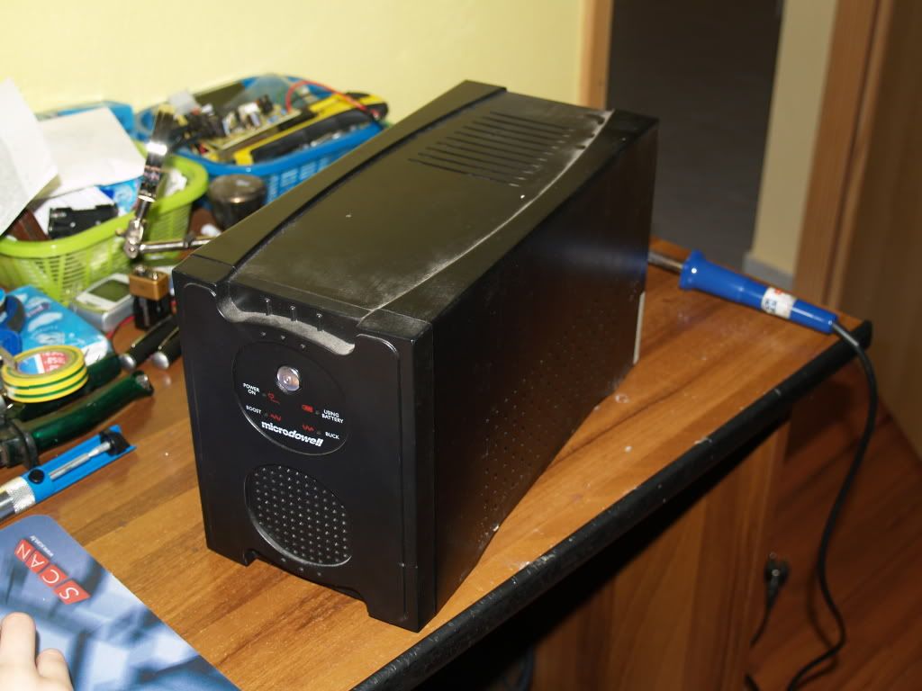
Well, we have out PCB. With HV AC running through it, we must have a box to put it in.
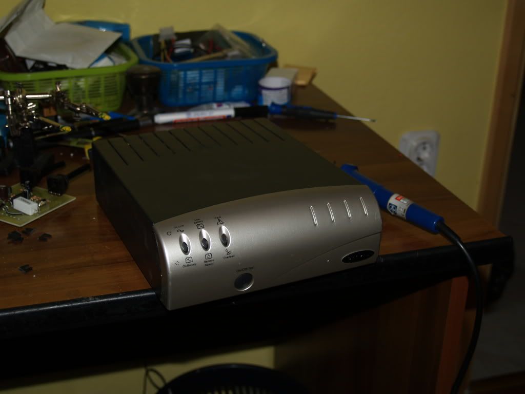
As I promised in the last thread, I managed to dig up a UPS (three pf them, this one was the prettiest )
)
Taking a look at the back side already tells us more about internal construction.
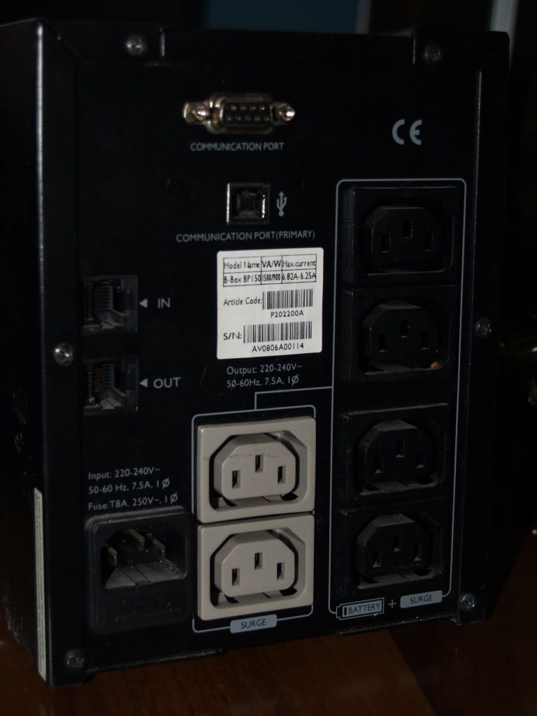
We can see that there is a total of 6 computers to be plugged in, and 4 of them can be sustained on the battery after a power loss.
After popping the hood, expectations were met.
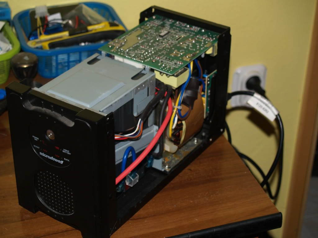
We have TWO lead accumulators, holding some kickass charge...
Well, since I got a crap load of UPSs because they were broken, I needed to see what was wrong.
OFC i tried connecting a computer to it...
OK, it did pass the power ... time to 'pull the plug' to see what happens...
GUESS WHAT!
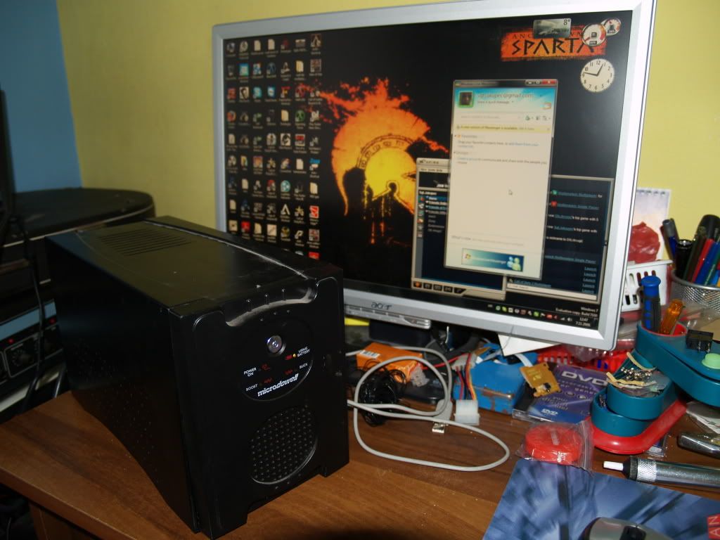
Still worked!
Well, I can see that I got cheated ... I already fired up the old soldering iron in hope I will get to do some rapairing and stuff. But obviously I was scammed! I 'm never doing business with that guy again!
Now, first intention of opening it up, was to see if I can put entire PCB and connections inside it. However, doing so would require drilling the front pannel for the pots and a bulb, ruining the overall look of it, and there was the lack of room to securely make the power inlet/outlet connections.
So I used and another UPS encloure:
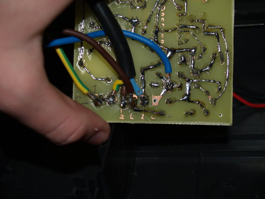
Ok, now to try to hoop up the power to my circuit.
It was tricky to solder FAT 220VAC wires to the pads...
Well, I gave it a test run without UPS only to determine if it is workin' or smokin'
YEP , one hell of a mess... HOWEVER nothing got blown to hell!
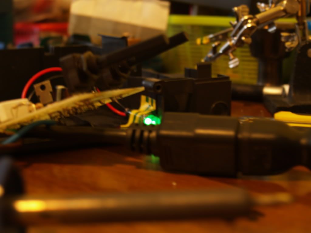
The light lighted up nicely...
Indicating that no repairs on power box are needed.
However, that is where my luck for today ended.
Light was on constantly as it should have... Once it reaches the desired temperature it should 'blink' indicating that only half of wave is passed through.
Well, it did not .
After following directions of the text and everything, it was simply on, no matter how i turned the pots.
Well after going through the article thouroghly, i figured out the problem.
When I was buying parts, I got my R3 and R8 values (according to the table) for 30-40 Watts, when i should have gotten the 20-30Watts values.
So, as much as unintended it is, I will have to make PART 3 next weekend.
I'm sorry folks to dissapoint you to the regulator project, but I hope I gave someone a good UPS ideas...
For now, I left everything as it was (regarding PCBs enclosure), enclosing it would only mean dissasemblying it next weekend.
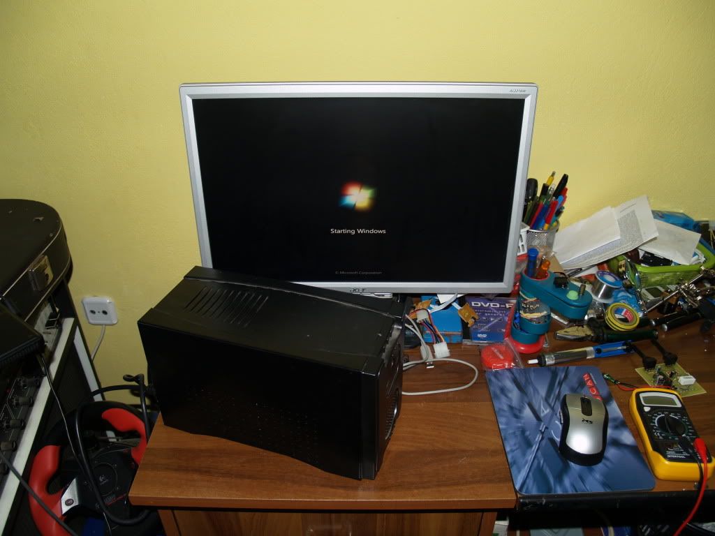
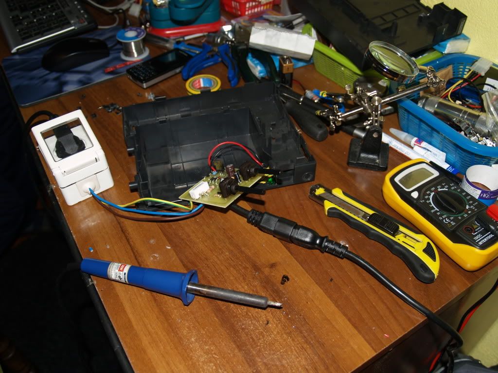
So, I only organised the wiring from power, USP and PCB, like so:
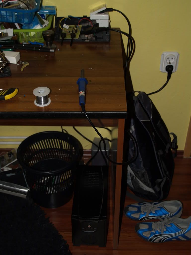
PLZ disregard my brothers shoes and bag
Under the table there is a USP, when turned on, turns on the soldering iron, also the PCB with the bulb on the far end of the table is indicating that it is working.
Now, even if the regulation was temporarely delayed, the Uninterruped Soldering Station part of the project worked.
When the plug is pulled, iron still maintains its operation.
I haven't gave it a benching, since the regulation circuit is non functioning. Well, PREMATURE end of PART 2 <HERE>
Through the week, I will buy the correct resistors to repair my regulator,
And the next weekend, finally
THE TEST RESULTS, and testing the runtime of UPS.
Well, although I have given my iron nothing more than a pretty switch box, it is stull usefull to have it working when the power goes out!
Until next weekend folks, my sincere apologies, and best of luck in all of your projects (unlike my luck).
Enjoy!
This is my sequel to previous thread, in which I went over some basics of making a PCB, along with presenting my new project, temperature regulator for cheap irons.
Well, in previous thread we stopped when we had the components soldered on.
The reason we stopped is because I was missing some parts and had tough luck (running out of soldering wire, breaking only 1mm drilling bit, PCB turned out bad).
Well, we have out PCB. With HV AC running through it, we must have a box to put it in.
As I promised in the last thread, I managed to dig up a UPS (three pf them, this one was the prettiest
)
Taking a look at the back side already tells us more about internal construction.
We can see that there is a total of 6 computers to be plugged in, and 4 of them can be sustained on the battery after a power loss.
After popping the hood, expectations were met.
We have TWO lead accumulators, holding some kickass charge...
Well, since I got a crap load of UPSs because they were broken, I needed to see what was wrong.
OFC i tried connecting a computer to it...
OK, it did pass the power ... time to 'pull the plug' to see what happens...
GUESS WHAT!
Still worked!
Well, I can see that I got cheated ... I already fired up the old soldering iron in hope I will get to do some rapairing and stuff. But obviously I was scammed! I 'm never doing business with that guy again!
Now, first intention of opening it up, was to see if I can put entire PCB and connections inside it. However, doing so would require drilling the front pannel for the pots and a bulb, ruining the overall look of it, and there was the lack of room to securely make the power inlet/outlet connections.
So I used and another UPS encloure:
Ok, now to try to hoop up the power to my circuit.
It was tricky to solder FAT 220VAC wires to the pads...
Well, I gave it a test run without UPS only to determine if it is workin' or smokin'
YEP , one hell of a mess... HOWEVER nothing got blown to hell!
The light lighted up nicely...
Indicating that no repairs on power box are needed.
However, that is where my luck for today ended.
Light was on constantly as it should have... Once it reaches the desired temperature it should 'blink' indicating that only half of wave is passed through.
Well, it did not .
After following directions of the text and everything, it was simply on, no matter how i turned the pots.
Well after going through the article thouroghly, i figured out the problem.
When I was buying parts, I got my R3 and R8 values (according to the table) for 30-40 Watts, when i should have gotten the 20-30Watts values.
So, as much as unintended it is, I will have to make PART 3 next weekend.
I'm sorry folks to dissapoint you to the regulator project, but I hope I gave someone a good UPS ideas...
For now, I left everything as it was (regarding PCBs enclosure), enclosing it would only mean dissasemblying it next weekend.
So, I only organised the wiring from power, USP and PCB, like so:
PLZ disregard my brothers shoes and bag
Under the table there is a USP, when turned on, turns on the soldering iron, also the PCB with the bulb on the far end of the table is indicating that it is working.
Now, even if the regulation was temporarely delayed, the Uninterruped Soldering Station part of the project worked.
When the plug is pulled, iron still maintains its operation.
I haven't gave it a benching, since the regulation circuit is non functioning. Well, PREMATURE end of PART 2 <HERE>
Through the week, I will buy the correct resistors to repair my regulator,
And the next weekend, finally
THE TEST RESULTS, and testing the runtime of UPS.
Well, although I have given my iron nothing more than a pretty switch box, it is stull usefull to have it working when the power goes out!
Until next weekend folks, my sincere apologies, and best of luck in all of your projects (unlike my luck).
Enjoy!


