Welcome to Laser Pointer Forums - discuss green laser pointers, blue laser pointers, and all types of lasers

LPF Donation via Stripe | LPF Donation - Other Methods

Links below open in new window

ArcticMyst Security by Avery

Pioneer 112D open can laser diode V-I-P plot

drlava

0
Joined
Mar 7, 2007
Messages
1,152
Points
0
It appears that perhaps there may be more than one diode type in these burners KAZ over at P.L. is reporting different wavelength and Vds than I am seeing here. I ordered several burners and so far the wavelength has been 658-660 nm (measured with a monochromator). Also the lasing thershold is 75-80mA.

Here is a non-TEC cooled plot (diode temp measured from the back of the diode 20C at the start of the test, 27C at the end) of a run in my automatic tester:


As you can see, it's an impressive diode.


chimo

0
Joined
Jun 20, 2007
Messages
650
Points
0
Great graph, I would have expected a more shallow V curve. Very interesting. Thanks for posting that. Please tell us about your automatic tester.
 

CHP

0
Joined
Sep 30, 2007
Messages
74
Points
8
Could you please describe or post a picture of your heatsink.
 

drlava

0
Joined
Mar 7, 2007
Messages
1,152
Points
0
The tester is self-built; it utilises a Scientech 365 meter and a national instruments DAQ board with custom software and hardware. Current resolution is 0.122mA in the 500mA range and the scientech has a res of 1mW on the 2W range used for this test. The test was done with current increments of 5mA, and the output was allowed to settle before taking the measurement point each sample.

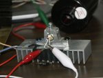
Below you can see the heatsink used. It's built so swapping the diode/mount is easy, heatsinking is adequate, and the blue wire is a thermistor going to the back of the diode with thermal paste at the end.
 

Attachments

  • testersink.jpg
    testersink.jpg
    110.3 KB · Views: 1,038

Benm

0
Joined
Aug 16, 2007
Messages
7,896
Points
113
Nice graph!

I'm a bit surprised by the large forward voltage on higher currents, but i guess its nothing to worry about (looks like it has internal resistance somewhere).

Would you reckon this diode can operate for a long time somewhere near the upper end of the graph (say 400mA/250mW)? That seems well in the linear range of the plot, but i still wonder how long it will last - an hour, a day, a week?
 

drlava

0
Joined
Mar 7, 2007
Messages
1,152
Points
0
I agree about the diode V slope, the resistance can be calculated directly from the graph. Interestingly, when a diode dies, the voltage across it drops slightly.

Would you reckon this diode can operate for a long time somewhere near the upper end of the graph (say 400mA/250mW)? That seems well in the linear range of the plot, but i still wonder how long it will last - an hour, a day, a week?
This is running as we type!
 

jayrob

0
Joined
Sep 21, 2007
Messages
9,862
Points
113
Man that is some nice testing equ. that you have there! Hemlock Mike said that you are getting one of these 4 X blu-ray drives:
LG Electronics GGW-H20L
Will you by any chance be plotting a similar graph of that diode? Awesome stuff...
Jay
 

phenol

0
Joined
Oct 30, 2007
Messages
533
Points
18
I agree about the diode V slope, the resistance can be calculated directly from the graph. Interestingly, when a diode dies, the voltage across it drops slightly.
thats an interesting observation. when it dies, the optical yield is nearly zero, but the current pumped in the junction is the same, so is the Vf /initially/. Therefore, the total input power is the same as when it lased. now that it doesnt lase, no optical power is emitted which effectively increases the heat generated by the chip, which in effect results in lower Vf.... does it sound plausible? ::)
 

Gazoo

0
Joined
Jun 9, 2007
Messages
3,206
Points
38
DrLava, thank you.. :) Your graph matches almost exactly with my testing at 350ma's.....2.83 volts and 220mw's output with an acrylic lens. Are you using a glass lens?

Also when I ran mine at 600ma's it did not die while it was running. It died when I turned it off, then back on again and it was a nice LED. It takes around 900ma's to totally kill the diode. Thanks again for your testing.
 

Benm

0
Joined
Aug 16, 2007
Messages
7,896
Points
113
phenol said:
I agree about the diode V slope, the resistance can be calculated directly from the graph.  Interestingly, when a diode dies, the voltage across it drops slightly.

thats an interesting observation. when it dies, the optical yield is nearly zero, but the current pumped in the junction is the same, so is the Vf /initially/. Therefore, the total input power is the same as when it lased. now that it doesnt lase, no optical power is emitted which effectively increases the heat generated by the chip, which in effect results in lower Vf.... does it sound plausible?  ::)

Sounds feasible to me - the efficiency of laser diodes is so good it actually makes a difference if light makes it out or not.

Also when I ran mine at 600ma's it did not die while it was running. It died when I turned it off, then back on again and it was a nice LED.

This is an interesting thought. I actually had one diode die recently at very moderate driving (a sony 16x at 220 mA or so), also at the moment i switched it on (or off, no way to tell but doesnt seem feasible). I checked the driver for any turn-on or turn-off voltage/current spikes, but found none, voltage rise was smooth (as expected considering the buffer cap) looking on the milisecond level.

There really is no sensible explanation why a diode would be likely to die the moment its switched on (unlike, say, a lightbulb), but somehow it seems the effect is there. I'm actually considering modifying my driver circuit to give it a soft start (100ms - 1s zero to full i guess).
 
Joined
Jan 7, 2007
Messages
6,309
Points
83
Super info, DrL.... I see that ugly little glitch at about 480 mA. That might be a clue for where to set it.

Mike
 

drlava

0
Joined
Mar 7, 2007
Messages
1,152
Points
0
Thanks guys, yes I will be running a 4/6x BR through this, it should have arrived the same day Mike's did.

I agree about definitely keeping it below 480mA. My duration test does cycle the diode on and off every 10 minutes, so the thermal stresses do play a role in verification at a power level. So far, it has survived over 6 hours at 250mW!

Test was with a glass lens.
 

Gazoo

0
Joined
Jun 9, 2007
Messages
3,206
Points
38
I was getting closer to 250mw's using the meredith glass lens, closer to 220mw's using an acrylic lens. Maybe my 112D diode is a "hot" one. Or maybe it is the differences in lenses. Not sure if your lens is AR coated or not but the meredith glass lens.
 

drlava

0
Joined
Mar 7, 2007
Messages
1,152
Points
0
yes, the lens is the AR coated aixiz. There might be significant variation in the batches of diodes, the threshold voltage tells some of the story. These had a threshold of about 78mA, some diodes reported to have a threshold of 72mA have a steeper slope. I'll have to pick up a meredith I guess and see how different it is.
 

phenol

0
Joined
Oct 30, 2007
Messages
533
Points
18
it is surprising how different some 20x LDs can be: my lite-on one has Ith of about 56mA and much higher Vf /2.60V at 170mA/ compared to 20x LGs with Ith =75-77mA and Vf=2.43V at 200mA. the lite-on's power curve is probably steeper, but i dont know how far up it would extend compared to the seemingly cooler at lower currents LG.
drlava, it would be interesting to also record the Ith in this life test at a fixed temperature. If Ith goes up with time, this is a sign that the LD is due south....
 

drlava

0
Joined
Mar 7, 2007
Messages
1,152
Points
0
phenol said:
it is surprising how different some 20x LDs can be: my lite-on one has Ith of about 56mA and much higher Vf /2.60V at 170mA/ compared to 20x LGs with Ith =75-77mA and Vf=2.43V at 200mA. the lite-on's power curve is probably steeper, but i dont know how far up it would extend compared to the seemingly cooler at lower currents LG.
drlava, it would be interesting to also record the Ith in this life test at a fixed temperature. If Ith goes up with time, this is a sign that the LD is due south....

I do record this Ith during the life testat 10 minute intervals. So far, though, it has never shown a change, even on the ramp that is the diodes final.

Also, those of you who noticed the high forward resistance of the diode, you were right! theres a series resistance in my setup of 0.336 ohms that was unaccounted for in the plots. This amounts to an increase in Vd of 0.168 at the 500mA mark, that should be subtracted to find the true Vd. This will be compensated for in future plots, and previous data will be corrected.


Top