Welcome to Laser Pointer Forums - discuss green laser pointers, blue laser pointers, and all types of lasers

LPF Donation via Stripe | LPF Donation - Other Methods

Links below open in new window

ArcticMyst Security by Avery

Need to amplify this

Joined
Jan 12, 2008
Messages
3,290
Points
83
I have a small multicolour LED circuit from and old keychain-thing that has three LED's (RGB). It has lots of cool effects that i want to convert into a lasershow by using three lasers, one red, green and violet (can't affoard blue) instead of the LEDs.
But this thing just doen't have enough power to do that, that LED's only take 20mA and I need 200 or more.

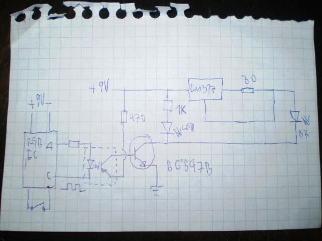
How can I make this work? My plan is to use transistors but i don't have a clue how to do it. I know that it uses pulses to fade the LED's up and down and they are square pulses.

Here are some pictures of it:
rgb030-1.jpg

rgb031-1.jpg


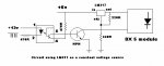
Here's how the RGB LED is connected, the black wire is common anode and the others are separete cathode channels for R, G and B (colour coded)
rgb032-1.jpg


I appreciate any help I can get with this because this is an exciting project! :D


Joined
Mar 8, 2008
Messages
2,669
Points
48
There's gotta be a way to get more power to it!! Hmmm... maybe follow the traces and see what the resistor values are. The problem with this is that it probably uses a microcontroller or some other sort of IC (which I dont know a damn thing about btw) and changing resistance may do something other than give you more power. This one is a bit over my head without being able to see it in person.
 
Joined
Jan 12, 2008
Messages
3,290
Points
83
Actually I've short the the existing resistors on the channels and still nothing, instead I put my own resistors on the LED. All they do is to balance the colours.

And there's no way that the IC can take such abuse at >200mA. :(

BTW, I plan to power the lasers with the DDL driver with 12V. Somehow that is.
 
Joined
Jul 24, 2007
Messages
2,749
Points
0
Funnily enough I am doing the same thing, ;) you need to run the output through opto isolators and use NPN transistors to turn the LD supplies off and on.....

I have attached a drawing I did for a previous project, you will need 3 opto's one for each colour, do not worry that it says 12v for the input. You need to find out whether the circuit is pos or neg common and wire the existing output resistors acordingly....

I hope that helps.

Regards rog8811

[edit]if I had read the whole thread I would have seen that you are using 12v anyway and you know that they are common neg, so the resistors go to the positive input of the opto ;)[/edit]
 

Attachments

  • green_driver02.jpg
    green_driver02.jpg
    48.2 KB · Views: 516
Joined
Jan 12, 2008
Messages
3,290
Points
83
VERY nice rog! :eek:

I'm gonna look through all of my electronic-boxes, I belive I'v got some opto isolators. Alteast two identical.

What NPN's should I use? I've got some BC547B's. :)
 
Joined
Jul 24, 2007
Messages
2,749
Points
0
What NPN's should I use? I've got some BC547B's.

You need to check that they will handle the current draw of your drive circuits, so look up the data sheet. These days most NPN's seem to be good enough for our purposes but worth checking.

Regards rog8811
 
Joined
Jan 12, 2008
Messages
3,290
Points
83
I checked it and it can take max 200mA.

I just tried the circuit but it doesnt work. My circuit is different form yours so have a look:
002-1.jpg


When I press the button to start the cycle the blu-ray module and the LED indicator lights up and dimms down and the IC dies. The same thing happen every time I press the button.

The IC, transistor and opto isolator still works fine tho. When I short the photo transistor, the blu-ray module lights up. It should work, but it doesn't. :-/ What am I doing wrong?
 
Joined
Jul 24, 2007
Messages
2,749
Points
0
It shouldn't be a load issue as the opto input side is just the equivalent of an led..
...have you looked at the data sheet for the opto isolator to see if it is the correct output type?
Could you try replacing the driver/LD with just a LED to see if that works?

Regards rog8811
[edit]I have just remembered that I had the same trouble using this setup with a TTL output from a DAC, though it worked perfectly with the light organ I used for an earlier project, maybe someone can wade in with an explanation????? [/edit]
 
Joined
Jan 12, 2008
Messages
3,290
Points
83
OK Rog I fixed it, it works now. Sort of. :D

It's very cool, but it doesn't fade like the LED did. I'm uploading a video now so you can see the differnce, and I'm also testing some different modes.
But other that that it works GREAT! What I did wrong was that I forgot to put a resistor in series with the opto-LED, it was too much for the IC so it turned it self off.

I have a theory why it doesn't fade like I want. The pulses are a VERY high frequency so I think that the optoisolator works a little like a capacitor and just can't keep up...?

However, this is a big step forward to me and I'm very happy.

Video:
http://s279.photobucket.com/albums/kk149/FML_01/?action=view&current=rgb2001.flv
 
Joined
Jan 12, 2008
Messages
3,290
Points
83
BTW:

The problem is not that the blu-ray doesn't fade with the LED, because they are using two differnt channels.

What's wrong is that the blu-ray doesn't really fade, it's more like it's just turning on and off. That will not look very good when I combine it with red and green.

Also, the blu-ray module has some capacitors, maybe it's their fault. I don't know if I should remove them because of obvious reasons like voltage spikes and such.


PS, I don't have a datasheet on the optoisolator and I can't find one on google.
 
Joined
Jan 12, 2008
Messages
3,290
Points
83
Here's how it looks now:
http://s279.photobucket.com/albums/kk149/FML_01/?action=view&current=rgb3002.flv
I'm using a high power RGB LED (instead of lasers) with DDL drivers without any capacitors.

Here's a colour comparison with the LED's. The LED to the left is connected to the IC, making lots and lots of colours. The very bright LED to the right is and amplified doesn't behave like I want, it's more like 7 colours. The difference is very significant. Can it be fixed?
http://s279.photobucket.com/albums/kk149/FML_01/?action=view&current=rgb3001.flv
 
Joined
Jul 24, 2007
Messages
2,749
Points
0
I love the setup.....wires everywhere :).... You say the output is a square wave, did you put it on a scope to find that out? If so when the circuit is running does it change amplitude or frequency?

If amplitude this opto setup will not work, if frequency I would think that capacitors would make it slow to respond....

Regards rog8811
 
Joined
Jan 12, 2008
Messages
3,290
Points
83
Yeah it's quite a mess. ;D

I don't have a scope at home, but I took the IC to school to find out. To see what's going on is very tricky, but I can confirm that it changes the duty cycle of each pulse (like PWM) to change the intensity. I think that it also changes the frecuensy.

I don't use any capacitors ATM so that can't be the problem. Can you explain the funktion of the 470 ohm resistor? Maybe that has something to do with it.
 
Joined
Jul 24, 2007
Messages
2,749
Points
0
Can you explain the funktion of the 470 ohm resistor?
If it is the one on the input to the opto that you are refering to, it is just a current limiting resistor like you would use on any LED... I don't think that changing the value of it would make much difference. Somewhere on LPF is a link to a free downloadable oscilloscope that uses the sound card of your computer.... I will see if I can find it.

Regards rog8811

[edit]found it :) http://www.laserpointerforums.com/forums/YaBB.pl?num=1199369106/6#6 [/edit]
 
Joined
Jan 12, 2008
Messages
3,290
Points
83
Thanks Rog. That looks kinda complicated to me so I'm going to put that on hold, but I've saved the link. :)

So what am I doing wrong? I still belive that the optoisolator is too slow.
Have you tried this yet, and with what results?
 
Joined
Jul 24, 2007
Messages
2,749
Points
0
I won't be in a position to test the led drive circuit for a while yet..

That oscilloscope is going to be the quickest way to find out what is going on, it is nowhere near as complicated as it looks, you don't have to make probes, just use wires. BUT do make the diode/resistor circuit to protect your sound card.

If you have "Line in" on your sound card use one channel to the input of the opto and the other channel to the output side and see if they are the same.....

Regards rog8811


Top