Welcome to Laser Pointer Forums - discuss green laser pointers, blue laser pointers, and all types of lasers

LPF Donation via Stripe | LPF Donation - Other Methods

Links below open in new window

ArcticMyst Security by Avery

My LM3410x based Boost converters: Spark driver! PART 1

HIMNL9

0
Joined
May 26, 2009
Messages
5,318
Points
0
^ Probably, instability due to bad pcb or resonance ..... i made some trials, with 3410, and i can say you something, but i'm not a 3410 expert, nor an NS engineer :p, so, take them for that what they can worth.

First, as also IgorT said you, you need at least 10uF electrolitic tantalium, or 22uF standard electrolitic capacitor at the input, better if paralleled with a 220 or 470 nF ceramic capacitor ..... second, draw the pcb carefully, trying to keep all the connections the shortest possibles, especially the ones related to the coil and schottky diode, and the grounds ..... also, be abundant with the ground pads for heat dissipation ..... third, try to not put capacitors from the pin 1 (in your package is the switching pin) and the ground, but only from the positive output and the ground (i mean, from after the switching diode, and the ground pad), and also here, you need probably a good capacitor value ..... i was using 47uf tantalium paralleled with 1uf ceramic, at the output.

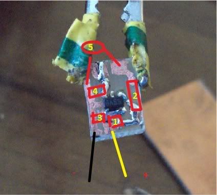
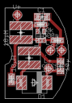
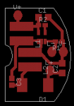
Also, don't place capacitors from the pin 3 and ground (practically, in parallel to the current sensing resistor), if you want a fast response current regulation ..... probably, you can place a 100nF capacitor there, but no electrolitics ..... anyway, the tests that i made in the past with this IC, showed me that it's a lot "permalous" about how you draw the PCB tracks ..... some of my prototypes also was not working, with no electrical defects, just cause it was not agreeing how i had placed the components and tracks ..... where instead, redrawing it for keep the coil the nearest possible to the pins 1 and 5, it worked with the same circuit and components ..... there's nothing to do, it's permalous :p


Joined
Feb 5, 2008
Messages
6,252
Points
83
I did made my PCB following the datasheet guidelines as close as possible, I will draw you my components layout in paint, wait a second.

sparkPCBcomponentplacement.jpg


1. Coil
2. schottky
3. input cap
4. current regulation resistor
5. output cap, ceramic disk

I know... I know it all don't stone me to death yet. I need much larger capacitance at input and also need cap across the diode also.
I already have a new revised PCB in my mind, which does not require big ceramic disk cap, and also revised coil placement so I can use bigger ones (4x4x2 milimeter that got shipped today from coicraft free samples, yay! :D ) these new ones are 4.7 uH, but 1.5 A current rating. Hopefully they will suffice.

If you want I can TRY to draw out new PCB layout for ya, but it is kinda difficult on lappy touchpad.
 
Last edited:

ReNNo

0
Joined
Mar 27, 2009
Messages
589
Points
0
Use EAGLE and try to design PCB.
Then you can print lot, lot of these PCBs on one A4 photo paper. (With laser printer)

It's much easier than drawing PCBs with hand and all lines will look much more professional.
 
Joined
Feb 5, 2008
Messages
6,252
Points
83
Use EAGLE and try to design PCB.
Then you can print lot, lot of these PCBs on one A4 photo paper. (With laser printer)

It's much easier than drawing PCBs with hand and all lines will look much more professional.
Told ya, I ain't got no laser printers so ...

I am working with what I have, Never failed me !
Let's first get the prototype done. As soon as I have my bluray finished with this driver, and powered with one 18650 lithium ion cell, then we can worry about professional looks.
First I need a proof of concept.
 

ReNNo

0
Joined
Mar 27, 2009
Messages
589
Points
0
Yes, but every copying shop can do this for you for less than $1.

I agree, first you need to finish and test driver and then you can do something to improve PCB looking and quality.

This is just my advice for you because this method is cheap and very easy.
 
Joined
Feb 5, 2008
Messages
6,252
Points
83
Agreed 100%.

Well, once I get it to power my PHRs, then I will try to make nicer PCBs, preferably with 'SPARK' written on them, that is so cool when you have the name of the driver on your PCB.
 

HIMNL9

0
Joined
May 26, 2009
Messages
5,318
Points
0
Wait, what current you was trying to get from the unit, and what type of coil ?

You need to keep in consideration the saturation current, working with boost drivers, and not just the output current, for the coil ..... and the small "brick shape" coils that you can find on power lines, are not good for this ..... there are a lot of values to keep in consideration, for calculate the saturation current, Vout, current, frequency, and others, but for give you a quick help, just considerate a good current for the coil, if it's from 3 to 5 times the current that you want to get for the load (this is not a "scentific value", just a guideline) ..... basically, anyway, never less than 3 times (and this can also explain the instability of your tests, the coil saturate and the unit stop to regulate correctly) ..... can say, indicatively, that you need at least a 10uH 1,5A coil, for get a stable 200 / 300mA out at around 6V, with a decent stability and ripple factor .....
 
Joined
Feb 5, 2008
Messages
6,252
Points
83
Wait, what current you was trying to get from the unit, and what type of coil ?

You need to keep in consideration the saturation current, working with boost drivers, and not just the output current, for the coil ..... and the small "brick shape" coils that you can find on power lines, are not good for this ..... there are a lot of values to keep in consideration, for calculate the saturation current, Vout, current, frequency, and others, but for give you a quick help, just considerate a good current for the coil, if it's from 3 to 5 times the current that you want to get for the load (this is not a "scentific value", just a guideline) ..... basically, anyway, never less than 3 times (and this can also explain the instability of your tests, the coil saturate and the unit stop to regulate correctly) ..... can say, indicatively, that you need at least a 10uH 1,5A coil, for get a stable 200 / 300mA out at around 6V, with a decent stability and ripple factor .....
Well IgorT said he used 4.7 uH with LM3410Y version , which is 500 KHz switching freq.

I got free samples of 4.7 uH and around 1.5 A. Shielded, 4x4x2 milimeter dimensions.
Trying to power a PHR at 100mA from one lithium ion, no more. Or maybe I would like to make it capable of pushing 200 mA for 6x.
 
Joined
Jul 30, 2010
Messages
21
Points
0
Hi all

I'm building a constant current regulator to drive a LED using LM3410 in SEPIC mode. I'm using the circuit nº6, page 24 of the datasheet with the folowing changes in components:
LM3410XMFE SOT23-5 (instead of LM3410XSD LLP);
ON MBRS320T3G rated 0,4Vf 3A (instead of DFLS120L)
R1=1ohm to provide around 200mA

I use a CREE MC-E as a load. Powered everything with 3 AA batteries (4,5V), the LED made some flick and nothing... I saw some smoke comming between the inductors and powered everything off. I tryed another design and build another prototype. The same: some flick on the LED and some smoke... I notice that the inductors heat a lot... I double checked everything and seems to be connected ok. Do you think the PCB design could be the cause? I'm using Eagle to draw a single side PCB. Can you provide help? Thanks
 

HIMNL9

0
Joined
May 26, 2009
Messages
5,318
Points
0
Uhm, yes, PCB design is critical, for high frequency boost/switching drivers ..... also the coil need to hold the switching current, not just the output current (just as example, a 300mA circuit have usually as "suggested", a coil with a saturation current of 2 to 3 A)

Programs like Eagle and similars cannot manage these types of PCB, you need to do it "handy", probably .....
 
Joined
Feb 5, 2008
Messages
6,252
Points
83
Uhm, yes, PCB design is critical, for high frequency boost/switching drivers ..... also the coil need to hold the switching current, not just the output current (just as example, a 300mA circuit have usually as "suggested", a coil with a saturation current of 2 to 3 A)

Programs like Eagle and similars cannot manage these types of PCB, you need to do it "handy", probably .....
Hmm , odd...

He says, smoke between the inductors...
Are you using multiple inductors?

If so, get rid of them, and go to Coilcraft.com, and get appropriate coils suggested in the datasheet , or any of your desire if you know what you need.

Listen to HIMNL9 too, he knows more about that stuff than me.
 
Joined
Jul 30, 2010
Messages
21
Points
0
Uhm, yes, PCB design is critical, for high frequency boost/switching drivers ..... also the coil need to hold the switching current, not just the output current (just as example, a 300mA circuit have usually as "suggested", a coil with a saturation current of 2 to 3 A)

Programs like Eagle and similars cannot manage these types of PCB, you need to do it "handy", probably .....

I'm using 4.7μH 3A from Coilcraft (exactly the ones mentioned on the LM3410 datasheet)... I tryed to make the design traces short and put everything close enough... See attached eagle image
 

Attachments

  • lm3410_1.png
    lm3410_1.png
    5.5 KB · Views: 225
  • lm3410_2.png
    lm3410_2.png
    1.9 KB · Views: 163
Joined
Jul 30, 2010
Messages
21
Points
0
Hmm , odd...

He says, smoke between the inductors...
Are you using multiple inductors?

If so, get rid of them, and go to Coilcraft.com, and get appropriate coils suggested in the datasheet , or any of your desire if you know what you need.

Listen to HIMNL9 too, he knows more about that stuff than me.

No multiple inductors, just 2 single ones from coilcraft, like on the SEPIC design.
Maybe i'll sacrify one of the boards and see which component burns... :yabbem:
 
Joined
Feb 5, 2008
Messages
6,252
Points
83
No multiple inductors, just 2 single ones from coilcraft, like on the SEPIC design.
Maybe i'll sacrify one of the boards and see which component burns... :yabbem:
It's possible that you shorted something out - STO23-5 is very tiny after all.

You should first recheck all your connections for shorts and OCs.
All that is really really tighly crammed on your board, too many possibilities of shorts.
 
Joined
Jul 30, 2010
Messages
21
Points
0
It's possible that you shorted something out - STO23-5 is very tiny after all.

You should first recheck all your connections for shorts and OCs.
All that is really really tighly crammed on your board, too many possibilities of shorts.

Yes, i already triplechecked everything, it seems all ok... And since this is the second PCB with a new design, it was to much coincidence the same error twice (shorts, oc...)...
I couldn't find the source of the smoke, but it seems that came from C3 (no more smoke, i think i killed some component)
I'll try another design for the PCB, like the one in the evaluation board (large sqares of copper instead of wires).
 
Joined
Oct 25, 2007
Messages
221
Points
0
PCB design which is not optimal shouldn't cause it to blow. It will affect efficiency and regulation though. Just make sure you read the datasheet through and through so you dont misinerpret the layout.

If you blew a capacitor, was it a tantalum on reverse polarity?

BTW, I found that in sepic config, the lm3410 can't seem to handle the same currents it can in boost mode. The datasheet doesn't give many specifics or examples as to what it is capable of as a sepic converter.


Top