Welcome to Laser Pointer Forums - discuss green laser pointers, blue laser pointers, and all types of lasers

LPF Donation via Stripe | LPF Donation - Other Methods

Links below open in new window

ArcticMyst Security by Avery

Modifying the DDL circuit

Joined
Dec 28, 2007
Messages
185
Points
18
Ok i extracted another diode from a scrapped DVD burner. It worked fine til i turned up the pot(i think too much) and now i got a LED.

So i ask, how can the DDL driver be modified so that there is a threshold in power output and if i was to turn the pot to max it will not cause the diode to burn out? What kind of resistor would do the job? I hear people running around 150 - 250mA for the red burners so i want to configure the driver to be able to push out ~275mA at full put turn and the diode should still cope with that.

Any ideas?

Remember im pretty noob at this stuff.


chido

0
Joined
Dec 4, 2007
Messages
1,918
Points
0
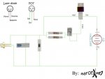
Can you post a pic of your driver, the driver is dessigned to prevent that from happening by putting a resistor after the pot, but I guess you didn't do that. ;D
Here's a schematic:
 

Attachments

  • clip_image002_001.jpg
    clip_image002_001.jpg
    23.1 KB · Views: 18,749
Joined
Dec 28, 2007
Messages
185
Points
18
Ive got the two resistors in the circuit(2x10Ohm) Im putting 6v into it, 4xaaa duracells. What kind of mA should be the output when this circuit(in the above image) is hooked up to a 16x burner diode? Whats a good dummy load for me to accuratley test the mA output without risking another diode?
 

chido

0
Joined
Dec 4, 2007
Messages
1,918
Points
0
Ok first, use 7.2v instead of 6, because with 6 the regulator will start dropping out pretty soon. Also try to use nimh batteries, 6 of them, because alkalines sag very quickly.
And second, how did you kill your diode by turning the pot to the least resistance if you had the resistors after the pot? :-?
To test your driver, go to this thread:
http://www.laserpointerforums.com/forums/YaBB.pl?num=1197651171
Most people here are driving their diodes at 250mA and have gotten pretty good results.
 
Joined
Jan 7, 2007
Messages
6,309
Points
83
Sarge --

You say "you hear of people running 150 to 250 mA". What were you running ?? Each diode and circuit can be different. What current did you drive the diode with ??

Mike
 
Joined
Dec 28, 2007
Messages
185
Points
18
I built an exact circuit as the image above. LM317T, 2 resistors in parallel after a 100ohm pot followed by the 1n4001, 32v 47uF cap and the diode extracted from a 16x LG burner. Im not sure if my multimeter measures current but i put it on the ~V setting and i got a reading of 2.8(which i assume is 280mA because i got a flashlight from DX(mdxl light) it reads at ~3.4 and ive read those lights take approx 350mA) but that reading was after the diode blew. I was using it and it didnt look bright enough. I turned it up abit it went a bit brighter but in comparison with the diode i pulled from a liteon drive it didnt look as bright. I then turned it up a notch and bang, it died.

This is the multimeter im using. Which setting do i switch it on do measure the current?

productLarge_5283.jpg
 
Joined
Oct 27, 2007
Messages
320
Points
0
HI if you measure your mA beyond 200mA, set your Multimeter selector to 10A DC and insert your red probe to "10A DC" slot and the black probe to "COM". and if you measure your mA lower than 200mA set the selector to 200mA and change the red probe from "10A DC" to "VohmmA". try that i suggest to use LED as your sample media before the actual LD.
 

chido

0
Joined
Dec 4, 2007
Messages
1,918
Points
0
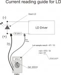
Just connect your dead LD to the circuit, and then connect a 1 ohm resistor to the positive leg of your LD and the other side to the positive wire of your circuit, then set your multimeter to mV and measure. Whatever you get in mV is going to be your current. Don't throw away your dead LD, you can use it to test all your circuits as it has the same resistance as a normal one.
Here's a pic, instead of using the 4 1N4001 diodes, connect your dead LD in series with the resistor:
PS: You don't have to use a 1 ohm resistor, you can use a 10 ohm, and then divide what you get in mV by 10. JUST LOOK AT THE LINK I POSTED ABOVE
 

Attachments

  • clip_image001_001.jpg
    clip_image001_001.jpg
    99 KB · Views: 901

chido

0
Joined
Dec 4, 2007
Messages
1,918
Points
0
Oh, and did you solder the capacitor to the LD, or did you leave it in the circuit board? There's a chance it might have somehow disconnected and reconnected, that's why your LD died. Also how long did you take to solder the leads to the diode, maybe the heat from the soldering iron damaged it, as you said at first it didn't get bright enough and that's why you kept turning up the current. Because, since you used the 2 10 ohm reistors, that limited the current to 250mA, so there's no way you killed your diode from excess current.
 

Gazoo

0
Joined
Jun 9, 2007
Messages
3,206
Points
38
That circuit really is a good test circuit, but you can use a dead laser diode in place of the IN4001's. And if you don't have a 1 ohm resistor, you can safely measure the current between the power source and the driver.

I do suggest you google how to use a multimeter.
 
Joined
Dec 28, 2007
Messages
185
Points
18
I just looked closer at the drive i ripped the diode from and it was a 12x burner...The diode was working fine when i fitted it into the unit. When i turned up the pot 3/4th of the way it died. I am now assuming that my driver is fine and that the problem was with the 12x diode which cant take 250mA?

mV on the dead diode was 2.7 - 2.8 = 270mA - 280mA?

Edit:

Ok i just tested it again this time with a 10Ohm resistor as the load. With the Pot on highest resistance voltage was 0.5v and mv was 0.3 or something

Maxed out the pot and the voltage was 1.89v and the mV was 3.5(assuming that mV is the V~ sign on the multimeter)
 
Joined
Aug 15, 2007
Messages
1,880
Points
0
I agree, you NEED to know how to use your multimeter before you break it.
V~ is AC volts. You are measuring AC volts, you should be measuring DC mV.

Should look something like this; a V and then a sign like this instead of the ~
___
- - -
and look for the 200m setting in that section.
 
Joined
Dec 28, 2007
Messages
185
Points
18
OK bluefusion i put it on that setting and the reading i got exceeded the limit so i had to bump it up to 2000m. I turned the pot to the highest resistance. I used a 10Ohm pot as the load and the output reading was 334 and on the lowest resistance on the same load i was reading in 1881. What are these figures? 334/10=33.4mA ~ 1881/10 = 188.1mA? Or do i have this wrong again

And again just to sort things out again, the diode i was using was extracted from a 12X DVD burner and NOT a 16X! I assume this is why it blew.

If my above readings are correct, if i go to the shop right now and buy a 20x burner, extract the diode and fit it in. What are the chances of it blowing due to excess current? Im going to get some components(well only 1n4001's) and build another exact driver and measure to see if i get exactly the same readings. Just need someone to confirm if the above looks correct.
 

chido

0
Joined
Dec 4, 2007
Messages
1,918
Points
0
I don't really understand the readings you got. :-?
As for the 20x burner, you can put a lot of current in it and it'll burn like crazy. Gazoo said the sweet spot for those diodes is about 400mA.
 

chido

0
Joined
Dec 4, 2007
Messages
1,918
Points
0
Ok man I'm going to tell you exactly what to do, ok.
First, grab your multimeter, plug the black probe to the com (the black jack) then take your red probe and plug it in the red jack.
Now take the diode you burnt out and your driver.
Set the pot in the driver to the highest resistance.
Connect the negative wire from your driver to the negative pin in your dead LD.
Then, take one of the 10 ohm resistors and put one of the pins to the positive pin of the LD.
And then take the other pin of the resistor and connect it to the positive wire coming from your driver.
Now take your multimeter look at the left side and set it in the spot where it says 200 mV.
Take your negative probe from your multimeter and place it in between the positive pin of the LD and the resistor.
Then take the positive probe and put it between the positive wire comming from your driver and the resistor.
Now slowly turn down the resistance from your pot, and look at the multimeter. Whatever number you get, divide it by ten, that's you current. ;)
 
Joined
Oct 27, 2007
Messages
320
Points
0
Hi i hope this illustration as of chido says.
 

Attachments

  • Current_Reading_guide.jpg
    Current_Reading_guide.jpg
    229.6 KB · Views: 693


Top