rkcstr
0
- Joined
- Dec 1, 2007
- Messages
- 1,368
- Points
- 0
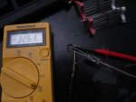
pseudolobster said:No worries, I'll check everything over with a mulimeter when I get home and try it out with a dummy load before trying again.
Alright, let me know how it goes because I'm really curious as to what's going on.
Also, have you tried the other, is it working OK?