Welcome to Laser Pointer Forums - discuss green laser pointers, blue laser pointers, and all types of lasers

LPF Donation via Stripe | LPF Donation - Other Methods

Links below open in new window

ArcticMyst Security by Avery

Micro laser driver - fits Aixiz/DX modules

rkcstr

0
Joined
Dec 1, 2007
Messages
1,368
Points
0
HZolly345 said:
What would be the neccessary out power/ma for 2x lithium ion batterys( 3.6v each, with 500ma each?) that is connected to a stonetek.com sony 16x burner diode? Like if I wanted the high outpust temp for burning, and a bright dot?

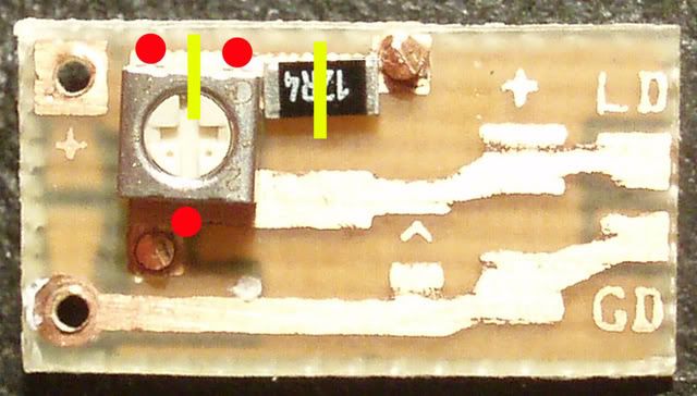
From what I understand, most people driver the the Stonetek 16x diodes with about 250mA, which from what Hemlock Mike graphed here, should give you about 175mW output, which is more than enough to burn. You can go higher than that, but unless you have a good cooling solution, the diode life may suffer.

BTW, lasers do not put out "heat" or have a temperature. These lasers are merely are high energy light that when absorbed by materials will heat them up, and if their combustion temperature is low enough, burn them.


Joined
Mar 30, 2008
Messages
6,058
Points
0
The New Stonetek Diodes run comfortably at 400ma with no issues. Hemlock Mike ran his for HOURS with no deviation :)
 
Joined
Oct 28, 2007
Messages
2,631
Points
48
SenKat_Stonetek said:
The New Stonetek Diodes run comfortably at 400ma with no issues. Hemlock Mike ran his for HOURS with no deviation :)


what was the mA output at 400mA?? THis is getting interesting!


LOL BTW: I just killed my blu-ray (pins pulled off the diode) so I popped my second one into the MXDL and upped the mA to 56. Its going at around 20mW now too.
 

chido

0
Joined
Dec 4, 2007
Messages
1,918
Points
0
The output at 400mA was about 245mW. :eek: I would recommend running these at 300mA though, (200mW) (since 400mA is the top of the curve) maybe 350mA which would give you about 220mW, but I don't think 20 extra mW is worth shortening the life of the diode. If it ran at 400mA for 14 hours without any problems imagine how long it would run by feeding the diode 300mA only. Here's the graph: (made by Hemlock Mike)

1239JL.jpg
 
Joined
Oct 28, 2007
Messages
2,631
Points
48
Ill go 400mA with good heatsinking.


Ill buy another and push it to death too, and graph it using the interface module (courtesy of knimrod)


regards,

amk
 

rkcstr

0
Joined
Dec 1, 2007
Messages
1,368
Points
0
Thought I'd repost the last page of discussion from this topic, as I still had the page up from before the crash.  It's still missing some of the third page, including my post about a protoype driver I made up, but it's not really working well yet, so I won't bother.  I also talked about a boost driver I made, which is where this kind of starting. Anyway, here it is:


rkcstr

Quote from IgorT on Yesterday at 4:56pm:
I was also thinking of using a 5V boost circuit for blue rays initially. But there are some, that actually have a higher Vf.

But such simple boost circuits really can be made tiny.

Hmm, yeah, that would be a problem.  But, out of the 11 I've had, all were between 4.3 and 4.9V, so I'm guessing that's relatively rare?  What do those burner diodes run at?


IgorT

I don't remember about the burner diodes for sure, i think it's higher. But when i power my blue rays with 220mA they take like 5.4V or so. (their treshold jumped and they are now undead)

Besides, burners absolutelly require current regulation, especially when a diode costs like $400.. You can't get away with voltage regulation there. You don't want a $400 thermal runaway..


Gazoo told me 5V is enough for any blue ray reader tho, and then he suddenly had one, which didn't work untill he replaced the 7805 with a 317 and saw more than 5V at the usual current.

I hope it's rare or even related to ESD or other damage, like with mine..


rkcstr

haha... diodes of the undead!  Yeah, I don't know, I gotta take some of my "dead" ones and see if I can make them undead, lol!  See what voltage they run at.


IgorT

I use the Frankenstein method..  1.6A seems to do the trick, and brings them back to life.. After that, the treshold is above 200mA and the power is very low, but they still make a beam with some fog. enough so, that i was able to take pictures of it.


rkcstr

Well, I took one of my "deader" diodes, that didn't lase very well at 40ma... hooked it up to my prototype driver so I could adjust output.  Well it was actually lasing well at about 70mA (but with those crappy artifacts that damages ones have), so I turned it up and definitely killed the thing around 100 something.  Well, kept turning it up, about up to 220mA (where the driver pretty much maxed) and it was lasing again, but not very brightly.  At ~30-40mA input (no output), it was at about 4.7V, but turning it up to ~150-200mA, the voltage jumped to about 5.9V!  It was probably causing the regulator to dropout at that voltage (needs +1.4V, but I'm only feeding it 6.3-6.5V, or about +0.5V), because the output wouldn't really go above 160mA at that point.


IgorT

Yeah, that sounds about right. Mine also stopped lasing at 40, had to use 70, but it died itself, and after that i just didn't care anymore and turned up the current on my PSU to 1.6A (seriously) and then the lasing treshold was 220.

Looks like at least they die consistently..  


And i think the voltage was also close to 6V. I still use it occasionally for testing, and if i heatsink it well, it doesn't mind the currents. From this point on it doesn't get any worse, but drops in brightness with heat, as usual.


Kenom

I was going to recommend some Kind of current adjustability on yoru drivers.  Even the current one that works well would benefit from a potentiometer.  some means of adjusting the current.


rkcstr

My original design had a potentiometer, but I found a problem.  When operating at high current output, the power dissipation of the potentiometer is too high.  When running at 400mA, it's disspating 1/2W.  Also, since the driver tends to run hot, the increased operating temperature also decreases power handling capability.  Combine that with the fact that any pot small enough to fit my driver isn't rated more than 1/4W, I felt it was too much of risk to include it, and instead use 1W worth of resistors to set it manually, just to be safe.

Reason for my paranoia is most due to a test of my original circuit which I had going at about 315mA, a small pot (really underrated at 0.1W) controlling the current failed and took my open-can diode with it. While a 0.25W pot would certainly hold up longer, I don't want to risk someone blowing a diode with my driver.

But, it is possible to modify one of my drivers to use a 3mm pot (though I obviously won't recommend it) by removing the resistors, making two cuts on one of the resistor pads and putting the pot and a series resistor on there.  Here's a pic of how that would work:

mod.jpg
 

drlava

0
Joined
Mar 7, 2007
Messages
1,152
Points
0
rkcstr said:
[quote author=BlueFusion link=1206339013/15#19 date=1206503598]BAHAHA.
ok not to be rude
but you claim this as a low dropout device at 2.25 volts
yet a 317's dropout is only 1.7 volts
and my drivers can be filed down to fit these housings and have only 1V drop.
::)

These are considered 1V LDO regulators, but when regulating current, you must add the reference voltage (1.25V) to the "dropout", which makes the minimum input value 2.25V over your intented driving voltage.

Have you actually TESTED that your drivers produce proper regulated output at your claimed values?  They will continue to put out current, but it will decrease as you drop below the minimum input voltage.

Also, while I appreciate criticism, I don't appreciate ignorance.[/quote]

Since Blue was bragging about 'his' drivers here I had to interject that he did not do the circuit design that allows the 1V LDO.. and the schematic is posted for private use (when credit is given).
 

rkcstr

0
Joined
Dec 1, 2007
Messages
1,368
Points
0
Well, I've been trying to think of a good way to make these adjustable while staying within safe limits of the resistor ratings, and I think I have a solution.  Check it out, let me know what you think.  Don't mind the LM317 marking, it's same pin out as the chip I use, but mine wasn't available in the program.

MDsch.jpg


Basically, I parallel a resistor with a pot to divide the current and thus power, plus a 1/2W series resistor to limit peak current to about 416mA (assuming pot = 0 ohms).  The minimum for this circuit is just under 35mA, but that can be changed.

I've already made a mock-up of the board to test fit components and they fit.  The next step would be actually building one to test the circuit works as expected (mainly the resistors/pot can handle the power).  

The only negative aspect is cost increase for parts.  The pot is actually more expensive than the chip, plus the higher powered resistors are more expensive.  I'm trying to figure out costs, but it looks like the driver price would increase by about $1, maybe more, maybe less.
 

Jaeger

0
Joined
Nov 9, 2007
Messages
27
Points
0
I received mine today!
Thanks for the fast shipping!  Beautiful work!

You are my Idol for that soldering job!! Nothing short of AMAZING! Tiny components, perfectly placed and soldered simply beautifully!
 

rkcstr

0
Joined
Dec 1, 2007
Messages
1,368
Points
0
Great, I'm glad you're happy with them!

Haha, and the soldering wasn't done by hand, I don't think I could be that neat by hand.  I use solder paste and reflow in a small oven, which is quicker and easier than hand soldering, plus it looks neater since you can control the application of solder paste much more easily than with melted solder.  Sometimes the parts like to "wander" as the solder flows though, so I have to make corrections, which doesn't look as neat, but I try.  I want my drivers to not only work well, but look good too  ;)
 

rkcstr

0
Joined
Dec 1, 2007
Messages
1,368
Points
0
Well, I've tested a prototype of the circuit above (adjustable output design) at 420mA for over 20 min with no failure.  This was with a diode test load.  Output voltage was about 3.37V and input varied from about 6-6.5V.  Output current stayed stable fluctuating about +-1mA over the whole course.  This wasn't conducted with the actual parts, but with equivalents as follows:

20 ohm pot of the same series as the intended (which would be 100 ohms in actual) with 1/4W 33 ohm resistor in parallel with the pot (will be ~100ohms 1/4W in actual circuit), series resistor was 2x 3.9ohm 1/4W resistors stacked parallel (effective 1.95 1/2W, actual circuit would have ~2.5ohm 1/2W single resistor).  All of the rest of the parts would be identical.

Overall, I think it would work well as a driver and would negate the need to have "settings" meaning you order a driver and set it to whatever you like.
 

roSSco

0
Joined
Dec 5, 2007
Messages
649
Points
18
rkcstr said:
Well, I've tested a prototype of the circuit above (adjustable output design) at 420mA for over 20 min with no failure. This was with a diode test load. Output voltage was about 3.37V and input varied from about 6-6.5V. Output current stayed stable fluctuating about +-1mA over the whole course. This wasn't conducted with the actual parts, but with equivalents as follows:

20 ohm pot of the same series as the intended (which would be 100 ohms in actual) with 1/4W 33 ohm resistor in parallel with the pot (will be ~100ohms 1/4W in actual circuit), series resistor was 2x 3.9ohm 1/4W resistors stacked parallel (effective 1.95 1/2W, actual circuit would have ~2.5ohm 1/2W single resistor). All of the rest of the parts would be identical.

Overall, I think it would work well as a driver and would negate the need to have "settings" meaning you order a driver and set it to whatever you like.

That sounds like a winner! Any idea when these would be available? I'd probably get a half dozen or so. :D
 

daguin

0
Joined
Mar 29, 2008
Messages
15,989
Points
113
rkcstr said:
Well, I've tested a prototype of the circuit above (adjustable output design) at 420mA for over 20 min with no failure.

Nice!

Peace,
dave
 

rkcstr

0
Joined
Dec 1, 2007
Messages
1,368
Points
0
roSSco said:
That sounds like a winner!  Any idea when these would be available?  I'd probably get a half dozen or so.  :D

Well, as I stated, the price would have be more than the current.  The actual parts cost is about 100% more than the current one when purchasing parts for 200.  The pot itself is about 10% more than the regulator chip, which is currently the bulk of the cost for the driver.  But, I don't want to sell the driver for that much more.  Would everybody consider a $2.50 premium over the current one (making it $7.50 each) reasonable?

Also, last week (I think) I posted a small test load board that had 6 standard SMD diodes and a 1W 1ohm resistor for measuring current (or you can just use an ammeter).  It would be a great pairing with this driver so you can measure your current before hooking it up without risk of overdriving your diode (since the pot is one turn, a slip can cause it to jump).  I'm still trying to come up with a price for it, but it'll probably only be a few dollars, and you'd only need one for however many drivers.

If everyone is interested, I could order parts soon for the adjustable driver and the test load, but still offer the cheaper drivers until I run out of the parts for them.


Top