While (1) is an infinite loop and is a legitimate way of running the LPM. If it's easy/quick to update the firmware, might I suggest you do the following:
Can you make one of the unused pins switch every loop and hook up an LED?
(while (1){pin1=boolean; boolean=!boolean; ) in pseudocode
Can you also cycle through all of the numbers before the main loop starts? Just go through 1-9 on each 7seg display, waiting 100ms between each?
(Also, is it necessary to close and re-open the i2c port each time?)
Did you go through and configure the "fuses" of the chip to match the timings on the oscillator? I'm not sure if this is even applicable for Atmels but I know it is for PICs.
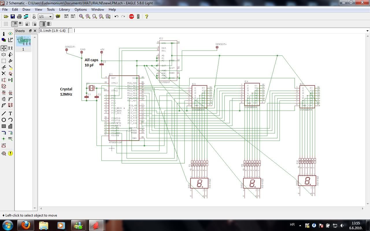
As I understand it, the 7seg display is controlled by 3 darlington array ICs? If so, you will need to make a new function to control which of the 7 segments is lit - does P0,P2,P3 refer to a pin? If so that's incorrect, you need a way to convert the number into ons and offs on the display.
While your knowledge on the subject is undeniable, so is my unability to use it, I am afraid.
You see, I like in small town which is 85 kilometers, or 2hour train ride away from the city I go to school in.
The programmer board for MCU is at school.
I am at home now.
My next visit to school will be tomorrow, when I have to present my work.
However - I am not doing the work only for the damned school, but for myself also - so basically everything you folks say will be used , if not before - then after the presentation to get this thing working and measuring some lasers.
When I take out the MCU from it's socket, and put one wire on +5V pin, and sweep it across the output ports (of the socket, where MCU is supposed to be ), the segments light up accordingly and respectively to ports touched, so there is no denying that the circuitry itself is alright.
I do not know what are the "fuses" you are mentioning please elaborate a bit more
")
Do you see the line :
Polje [] = { ..... } in the code?
The hexadecimal values in there , when converted to binary data corespond to segments that need to light up, for instance,
0xFF corresponds to
11111111
Each of the bits represent the segments in following order
A B C D E F G DP
which means that
FF
will light up all segments .
If for instance FE was to be used, all segments would light up except decimal point.
Decimal point never used though.
Wiring has been done on the schematic for ease of coding so ports x.1 - x.7 correspond to segment A-G (decimal point not used, port x.0 not used).
So no, P0, 2 and 3 are not pins, but ports, of which each contain 8 pins, but pin #0 is never used, leaving 1-7 pins for segments A-G (no DP).
"Stotice" , "desetice" and "jedinice" are croatian words for hundreds, tens, and ... how'd ya call it, displays the smalles-weight digit?
Anyhow, there are formulas for calculating those values from given input from ADC, for instance,
If ADC gives "123",
[First the value is multiplied by 2 (so I get range 0-510mW instead of 0-255mW, but 2 mW resolution, however Ignoring this part in my example for ease of understanding)]
Then, it's devided by 100, result is "hundreds", in our example, 1
Then, MOD 100 (result is number after decimal point, hence = 23), and then devided by 10, to get value of 2
Then MOD 100 to get 23, then MOD 10 to get = 3.
Numbers then should be sent to their respective ports...
Which is the three lines following,
P0 = ...
P2 = ...
P3 = ...
Name the values however you want, me and professor used croatian words.
Value of ADval (aquired data from ADC), midn you, is not Char as defined up there, me and professor changed it to Integer later, hwoever this is the code I saved in my email.
EDIT - PLEASE take into account what I've mentioned before, that i suspect that the "Polje []" is never actually used to define digits, before sending them to the ports, hence, no output comes, except brief flashes of A segment in Display1 (hundreds) and segment B in Display 2 (tens)
Polje[]is only defined there at the beggining but never actually used.
Is that correct?