phenol
0
- Joined
- Oct 30, 2007
- Messages
- 533
- Points
- 18


")
Benm said:At least provide some component values
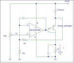
I have built some opamp based drivers, but this one is a bit puzzling at best. You scale down the sense current and then compare it to a reference that is variable from Vss to Vdd... i think that might be very finicky to adjust?
Right now the explanation is only on candlepowerforums... I'll give you the specs, pasted from there::-[a_pyro_is said:I should Prob. let a mod say so first, but I can't help myself. And please don't take this as a flame, just questions.
Is this Avery's Photo Hosting site? And what happened to the 10 post limit for links?
[benefit of the doubt] maybe he's planning to come back and post a few more details himself [/benefit of the doubt]
@Phenol
Please do come back and tell us a bit more. I LOVE seeing what others have made as it always gives me even more ideas. It's just disappointing to see a couple pics and no info about it other than what someone else pasted from another forum.
@Benm
You seem to know (as many do) a lot more about electronics than do I. would you be willing to start another thread describing a few of the constant current drivers you've mentioned elsewhere on the forum? ie an opamp, two transistors and a voltage divider, any others you think might be useful here.
a_pyro_is said:I should Prob. let a mod say so first, but I can't help myself. And please don't take this as a flame, just questions.
Is this Avery's Photo Hosting site? And what happened to the 10 post limit for links?
[benefit of the doubt] maybe he's planning to come back and post a few more details himself [/benefit of the doubt]
phenol said:Sorry. I never thought somebody might even be remotely interested in this circuit.
phenol said:Sorry. I never thought somebody might even be remotely interested in this circuit.
IgorT said:People are always interested in driver circuits.
Can you please also give a simplified explanation of the circuit?
- How much voltage are you feeding it?
- How much comes out on the other end (on the LD)?
- What are the minimum and maximum output current ratings?
Thanks!
a_pyro_is said:You seem to know (as many do) a lot more about electronics than do I. would you be willing to start another thread describing a few of the constant current drivers you've mentioned elsewhere on the forum? ie an opamp, two transistors and a voltage divider, any others you think might be useful here.
IgorT said:[quote author=phenol link=1193741215/0#5 date=1193766584]Sorry. I never thought somebody might even be remotely interested in this circuit.
True that. I managed to kill one IR LD because of such a current slug.CHP said:Don't eliminate the the capacitor in parallel with the LD because of the power up transient with this circuit. When power is first applied the op amp output voltage is zero and the darlington transistor becomes forward biased sourcing a current slug to the LD until the op amp output catches up and regulates the current. The duration of the slug of current is dependent on the slew rate of the op amp and the internal delay time. The capacitor should be sized to absorb the transient.
phenol said:True that. I managed to kill one IR LD because of such a current slug.
For shorter settling times high speed op amps should be used.