Benm said:I would also recommend using a 1k or so resistor across the diode, this improves turn-on behaviour as you crack the current up from zero using the pot.
Sorry to go a bit off topic, but why does that help?


Benm said:I would also recommend using a 1k or so resistor across the diode, this improves turn-on behaviour as you crack the current up from zero using the pot.


Benm said:[quote author=phenol link=1193741215/0#12 date=1193782823]
True that. I managed to kill one IR LD because of such a current slug.
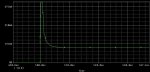
For shorter settling times high speed op amps should be used.
Benm said:[quote author=phenol link=1193741215/0#12 date=1193782823]
True that. I managed to kill one IR LD because of such a current slug.
For shorter settling times high speed op amps should be used.
a_pyro_is said:[quote author=Benm link=1193741215/15#15 date=1193838017]I would also recommend using a 1k or so resistor across the diode, this improves turn-on behaviour as you crack the current up from zero using the pot.
a_pyro_is said:Good to know a 1uF is enough, a lot of people are using 47uF Caps and while I'm sure that gives a softer start, it makes for a larger circuit.
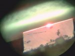
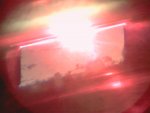
I aligned its objective with the eyepiece of the microscope.a_pyro_is said:Amazing pics! and from a webcam??? How in the world did you do that?
")
I aligned its objective with the eyepiece of the microscope.phenol said:[quote author=a_pyro_is link=1193741215/15#26 date=1194039480]Amazing pics! and from a webcam??? How in the world did you do that?
Very nice close up's. Thanks for sharing them..