Welcome to Laser Pointer Forums - discuss green laser pointers, blue laser pointers, and all types of lasers

LPF Donation via Stripe | LPF Donation - Other Methods

Links below open in new window

ArcticMyst Security by Avery

Knife-edging four NUBM44 in Lasertack micro module

Joined
Feb 25, 2010
Messages
1,643
Points
113
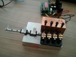
LSG....Yes....If the optics can be adjusted manually....then....that process can possibly be made automatic !! The most challenging piece of the puzzle...is done....of course....one can adjust the Plano Convex lens ...manually....this we know.

So...to set the convergence point....where the optics focus the beam....is easy. It then remains...how to do this...Automatically....and very inexpensive....and very miniature !!

OK....if we fall back on the ...er....ah..."enlightened concept "of using that which is already on the shelf and inexpensive due mass production....then...possibly...we hack a cheap digital camera with Auto focus !!

See... Understanding Camera Autofocus

I am sure we have plenty of members here who are Hackers !!! Let's see what you
"Hack-a-Day" wonders come up with !!! I speculate....such a concept may work ...with a single beam...not sure if a Quad combination will also work.

I have sooo many other projects...stacked up...I will not be working on this Auto Focus concept....but....maybe some one else will take up the challenge ....:D:D

CDBEAM
 
Last edited:


Joined
Feb 12, 2016
Messages
589
Points
63
Finally the 1st picture of the convergence spot!

I have attached the micro module to a 100x70x20mm Al plate and fixed the micro linear rail with 2 guides in front of it. Now the total mass of metal is 900g what should be enough to absorb the waste heat. Each guide has perfect size for Optlasers 3x C-lenses.

By manually sliding the PCX guide 4 spots on the white sheet of paper 2m away can be combined into one. But this spot is still 1cm long (and even longer at more distance), so 6x cylindricals would be really needed to make it kind of square. Indeed I have expected more square shape with 3x at least at 2m distance but here is what it is…

Anyway it burned through this paper at 2A current (making big hole as you can see). But did not burn when current was 0.5 and 1A for 5sec.

Now I will be waiting for Big Cylindricals pair from Bob.

Thank you Bob for sending!!!

I have also started a WTB thread about these in BST section a week ago but yet no answer. Looks like Bob was the only one who cared about beam correction at those old times, so no one else was buying C-lenses from Lazeerer and he disappeared…
 

Attachments

  • x.jpg
    x.jpg
    62.3 KB · Views: 62
  • y.jpg
    y.jpg
    37.9 KB · Views: 63
Last edited:
Joined
Feb 25, 2010
Messages
1,643
Points
113
:D:D Well...Yes....Terrawatt Labs has been " Forging / hammering " the beam's...for several years !! Optics are a stern Taskmaster....Optics have rules....which cannot be avoided.....Optics always cause some power loss....and they most times have some less than perfect solution or trade-off !! That is just the way it is !! :eg:

SO.....with your Quad project....See the attached diagrams.

With one (1) LD beam....the beam can be centered on the C-Lens
" Axis Point".....the second diagram depicts how your Quad set up
will present the four (4) beam in relation to the " Axis Point " on to the Plano Concave lens.....SOooooo..

The question in my mind...is ....will all four (4) beams be of equal focus....after they pass thru the Plano Concave lens ???

Now....we know we can have an effect on the beam geometry....as a function
of the distance from LD....to the Plano Concave lens.

SOoooo.....Maybe....you have the LD units...on the inside( LD2 and LD3)....set back....to equalize the focus !!! IF this is a problem !!

SO.... like this.....


LD1===>

..........LD2===>

..........LD3===>

LD4===>

Just thinking !! I am just questioning....for it always seems....as though....there arises a problem when working with Optical set-ups....and sometimes....if we are lucky....we can come up with a work around !!

Later,
CDEAM
 

Attachments

  • Cylinderical Lens_True Plane of Focus.png
    Cylinderical Lens_True Plane of Focus.png
    53.2 KB · Views: 48
  • Cylinderical Lens_True Plane of Focus with Quad Beams V1.png
    Cylinderical Lens_True Plane of Focus with Quad Beams V1.png
    48.9 KB · Views: 50
Last edited:
Joined
Dec 9, 2011
Messages
221
Points
28
Move your cylinder lens pair farther away from the diode for greater magnification. At some point you will exceed the aperture of the output lens. As mentioned earlier the distance from diode to telescope lens make a big difference on magnification.
 
Joined
Feb 25, 2010
Messages
1,643
Points
113
Finally the 1st picture of the convergence spot!

I have attached the micro module to a 100x70x20mm Al plate and fixed the micro linear rail with 2 guides in front of it. Now the total mass of metal is 900g what should be enough to absorb the waste heat. Each guide has perfect size for Optlasers 3x C-lenses.

By manually sliding the PCX guide 4 spots on the white sheet of paper 2m away can be combined into one. But this spot is still 1cm long (and even longer at more distance), so 6x cylindricals would be really needed to make it kind of square. Indeed I have expected more square shape with 3x at least at 2m distance but here is what it is…

Anyway it burned through this paper at 2A current (making big hole as you can see). But did not burn when current was 0.5 and 1A for 5sec.

Now I will be waiting for Big Cylindricals pair from Bob.

Thank you Bob for sending!!!

I have also started a WTB thread about these in BST section a week ago but yet no answer. Looks like Bob was the only one who cared about beam correction at those old times, so no one else was buying C-lenses from Lazeerer and he disappeared…

Well....I should have looked at your second pic....before I went off on a tangent about focus equalization !!!!!!!!!!!!!!!!!!!!!!!!!!!! Maybe ?????

Looks good to me....What is the spot width of all four beams combined ??? How far is the Far Field spot....from the LD 's ????

Now....what are the individual beam widths ??? Please cycle the individual LD1, LD2, LD3...and LD4.
on/off.

Do LD1 and LD4 have a wider geometry at the Far Field ....than LD2 and LD3.

Maybe all this Blah, Blah is a waste of time....as the current set-up may deliver results that are fine to you !!! ??? Actually....I expected worse....but am pleased to see such a tight Far Field of the combined beams !!

I bet that LD1 and LD4 have a slightly wider Far Field !! But then.....who cares !!! :tired::tired: I just have a personal passion for " hammering the D__
S___ outa the photons.

:twak::twak::twak:...bang, bang, bang !!! Whatever !!

CDBEAM
 
Last edited:
Joined
Feb 12, 2016
Messages
589
Points
63
I cannot switch on/off each LD separately, they are connected in series to ensure same current through each one. Also otherwise I would need 4 drivers what is too complicated for me... I like it easy way - one driver, one pair of lenses, here we go !!!

When not combined all 4 spots were looking similar on that sheet of paper next to each other and each was pretty close to 1cm in width. And I found it pretty difficult to get both lenses rotationally parallel, otherwise spots from left to right were on different heights. But I cannot show you pic because the setup is now disassembled - I want to restack the beams closer and make the group better centered than you can see on pics 3&4 in post 1.

But this will have to wait - a new working week is about to start.
 
Last edited:
Joined
Jul 10, 2015
Messages
9,907
Points
113
I had the idea of just for fun of building on 3 lengths of flat bar 3 corrected NUBM44's the center being screwed down stationary and the outer two being articulated.

The flat bar would be approximately 15mm wide by 5mm thick and 75mm long, or use 1/4 inch thick 1/2 inch wide by 3 inches long of what ever suits you, but for heat dissipation and vertical alignment it might be better to use trimable mirrors actuated by servos/galvos and have all 3 or more pre corrected lasers attached and adjusted for heat dissipation and alignment. This would never produce beam combining but converging which in my testing works great for setting cardboard alight.

56338d1497217031-knife-edging-four-nubm44-lasertack-micro-module-3x44toyb.jpg


56339d1497217031-knife-edging-four-nubm44-lasertack-micro-module-3x44toyc.jpg


11783-a.jpg


Even better would be to attach each corrected laser to a length of flat bar stock ( aluminum ) and arrange in a small tube/bazooka with the laser firing back toward the user where the galvo/mirror is mounted.

56340d1497217833-knife-edging-four-nubm44-lasertack-micro-module-3x44toyd.jpg
 

Attachments

  • 3x44toyb.JPG
    3x44toyb.JPG
    71.5 KB · Views: 124
  • 3x44toyc.JPG
    3x44toyc.JPG
    62.5 KB · Views: 122
  • 3x44toyd.JPG
    3x44toyd.JPG
    52.7 KB · Views: 125
Last edited:

BobMc

0
Joined
Apr 23, 2016
Messages
3,685
Points
113
Very interesting thread, world of good info here, following it closely. Keeping fingers crossed with this build. Should be one for the books! Best wishes. :)
 
Joined
Jul 10, 2015
Messages
9,907
Points
113
It's a dam shame the 06 diodes don't come in a can/window version, I have been getting them pretty cheap at auction and with the better divergence and price would have been nice to use.

I will warn everyone that those cheap 5 amp Chinese drivers do work but you MUST heat sink the hell out of them or they only work for 5 seconds until the overheat starts clipping.

----EDIT----

I would like to see a bunch of 44 diodes coupled to fiber, I have looked at fiber couplers, but I'm not sure what the beam requirements would be to make it work.
 
Last edited:
Joined
Feb 12, 2016
Messages
589
Points
63
Hi CDBEAM and others following this thread,

A little update about the experiment:

I am still waiting for the Big cylindricals you sent. Meanwhile I have readjusted the mirror mounts in order to have the whole 4 verticals lines group to be 3mm wide – not perfect but good to fit into 18mm wide PCV after 6x expansion (pic. 1)…

What I find strange is that if I change separation between OL 3x cylindricals from focusing position, the 4 spots at 2m distance are different in widths – the inner two are square and the outer two are long (pic. 2). So you seem to be right with what you said about the focal points – the axial aberration is here and it is pretty visible. And it does not mean that just focal distances are different – when I obscure the 2 inner lasers with paper (pic. 4), the 2 outer ones cannot be focused into a square spots (like 2 inner ones could) by moving lenses into different positions – the spot they coinside to is 1cm long line (pic. 3).

I am not sure if this must be due to the curvature of the given lenses (designed to perfectly expand only one beam passing through the lens center and not having that degree of curvature precision outside) or the “real life” beam behaviour at higher angles of incidence (called aberration).

But I would like to check this with other cylindricals and I also remember that 1-2 months ago RC or Alaskan pointed out some ebay sellers proposing 3 lens cylindrical sets – maybe those 3rd components were there to compensate for such kind of aberrations???
Could anyone remind me the link please?
 

Attachments

  • kk.jpg
    kk.jpg
    58 KB · Views: 44
  • ll.jpg
    ll.jpg
    26.1 KB · Views: 49
  • mm.jpg
    mm.jpg
    21.2 KB · Views: 52
  • nn.jpg
    nn.jpg
    68.2 KB · Views: 72
Joined
Feb 12, 2016
Messages
589
Points
63
Oh!
This does not look to be good for helping me - 3rd lens has horizontal curvature, it cannot correct the vertical aberration.
Maybe the right solution would be this one - but is expensive:
https://www.thorlabs.com/thorproduct.cfm?partnumber=AYL2520-A

Anyway I will continue my slow going experiments and maybe I can find a compromise between power and cost of the setup...

BTW What is the noon temperature in the place you work, Alaskan? Do you have to work outside? We have 35°C in Spain now what I find too high for me Russian born guy.
 
Last edited:
Joined
Dec 9, 2011
Messages
221
Points
28
Have you thought about "stacking" instead of "knife edging"? ---- instead of llll. Basically, turn the diodes 90 deg and the cylinders 90 deg. This way all beams go through the center of the lenses. Also when you converge the spots to overlap the aberration effects are much less.
 
Joined
Jan 29, 2014
Messages
12,031
Points
113
BTW What is the noon temperature in the place you work, Alaskan? Do you have to work outside? We have 35°C in Spain now what I find too high for me Russian born guy.

I'm near Erbil, Iraq which is Kurdistan country, they want to break off from Iraq next year. It gets hot outside here, 36-37 lately, I do work outside from time to time, but I usually wait until later in the afternoon for the temperatures to cool down some.

I am so much hoping you get to a point where you will show us a beam shot of all of the diodes turned full power on across a dark room :)
 
Last edited:
Joined
Feb 12, 2016
Messages
589
Points
63
Hi logsquared,

Will then the spot line not be long again because of stacking instead of aberration?
You are right, it might be a solution for converging at long range but to make such a set up I would need to adjust center hights of the on side lying lenses to the beams hight. What means inserting hight adjusting mounts between sliding guides and lying lenses and also produce a custom baseplate lifting the whole Quad block...

Alaskan,
Erbil sounds something from ancient Mesopotamian history to me. I read that today´s places were built not far from ancient cities: Mosul across the river from Ninevia, Baghdad not far from Babylon...

I would not expect the 4 separate beams to look much impressive - it is all about the convergence point to be really hot!
For really bright beam I am doing another 4x setup (with B-B dichro) but it is still classified (and not assembled)...
 
Last edited:
Joined
Dec 9, 2011
Messages
221
Points
28
Will then the spot line not be long again because of stacking instead of aberration?
You are right, it might be a solution for converging at long range but to make such a set up I would need to adjust center hights of the on side lying lenses to the beams hight. What means inserting hight adjusting mounts between sliding guides and lying lenses and also produce a custom baseplate lifting the whole Quad block...

You will have some aberration from the beams entering at a slightly oblique angle. It will be much less that the "knife edge" technique with some of the beams entering off center of the cylinder (especially when the beams are converging)

I would think you only need to shim the cylinders on the slide mount so their axis are the same (if the c-lens are different widths). Then shim the base to match.

I build a lot of projector modules, and stacking is really the only way to do it easily. Most projector guys are using 2mm FL collimating lenses. This way the stack is "shorter". However, 2mm lenses will X2 the fast axis (un corrected axis) far field spot.
 
Last edited:


Top