Welcome to Laser Pointer Forums - discuss green laser pointers, blue laser pointers, and all types of lasers

LPF Donation via Stripe | LPF Donation - Other Methods

Links below open in new window

ArcticMyst Security by Avery

Help please, external power for greenie

Joined
Jul 24, 2007
Messages
2,749
Points
0
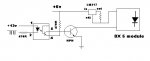
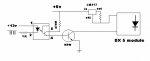
For complicated reasons I need to drive a 5mw green through an opto isolator. I have 12v and 6 volts avaiable. The opto is a 4N25, I also have LM317's to make regulators.

I managed to fry my first greenie when I got it totaly wrong :-[ My electronics expertise is not up to getting this up and running, can anyone help me with a circuit please?

Regards rog8811


Joined
Aug 3, 2007
Messages
342
Points
0
How did U want to Power your 4n25 LED to Start the laser?
I'm pshycic so...
Simple answer: PIN 1 is the LED pos. Use 5v from your (or CPU logic maybee )goes through 470 ohm series resistor to pin 1, grnd to pin 2.(opto is on now)

Now pins 4&5 can drive the base of a POWER NPN transisor to switch power to the
LM317 current regulator.

5v to 470 ohm to pin 4, pin 5 to base of the npn, emiter to ground, collector to ground of your laser driver! driver POS to power source.

Simple as brain surgery right?

CaPEESH? ;D ;D
 
Joined
Jul 24, 2007
Messages
2,749
Points
0
Power into the 4N25 diode I have done with the transistor on the circuit board that drives the whole thing ( I cannot use this directly to the LM317 as it is a 12v circuit that tends to sit above ground...I killed  my greenie when I tried using a pot to get it to come closer to ground  :().
It looks like I need to get myself a NPN then  :) I was trying to do it straight from the opto transistor...... As I said, i am at the limits of my knowledge here.

Thanks for the info laserrod

Regards rog8811
 
Joined
Jul 24, 2007
Messages
2,749
Points
0
@ laserrod I have drawn out the circuit that you described, could you please confirm this is what you meant.
 

Attachments

  • green_driver01.jpg
    green_driver01.jpg
    36.4 KB · Views: 97
Joined
Aug 3, 2007
Messages
342
Points
0
Man your good!  That is exactly what I wrote for you to do!
Great schematic!

Refinements:
I goofed ;D, so swap pin 4 and 5. It's backwards as U drew it. So col is 5 and emit is 4.
5 is Pos, 4 is Neg.
The 1st schem is better because the 317 is a true current limiter.(floating because it is not grounded). 2nd one looks wrong.

The 470 resistors should be increased because pin 1 & 2 current limit is .02 amp and pin 4 & 5. maybee .01 amp or so. Your not using 5v like I asummed.
I think it's best to find what the highest resistor that works is; and then go a little lower for insurance. Use less power, the better, RIGHT!

Don't blow you laser. First; test with  3 series diodes as Dummy load (laser)and make sure the NPN voltage drops to about .7 volts across collector (it's full on and saturated) & grnd and measure current equal or more to target LOAD.

And of course make sure your Opto LED grd is Isolated from Opto transistor grd. ::)
The whole idea here is to give that wonderfull 5,000 volts of isolation between switching circuit and the driven LASER circuit.


Cheers [smiley=beer.gif]
 
Joined
Jul 24, 2007
Messages
2,749
Points
0
Don't blow you laser. First; test with 3 series diodes as Dummy load (laser)and make sure the NPN voltage drops to about .7 volts across collector (it's full on and saturated) & grnd and measure current equal or more to target LOAD.

I can use my dead greenie possibly as it still draws 300ma?

Modified circuit follows.....
 

Attachments

  • green_driver01_001.jpg
    green_driver01_001.jpg
    35.9 KB · Views: 91
Joined
Jul 24, 2007
Messages
2,749
Points
0
Built, up and running.
Thankyou for the help Laserrod!

Regards rog8811
 
Joined
Jul 24, 2007
Messages
2,749
Points
0
UPDATE.... I have put up a movie on the XY from one speaker thread in multimedia, as you can see the greenie draws lines, I want it to flash more.

Question, would a capacitor across the laser module give the effect I want? If so any ideas of what kind of value?


Top