S
SenKat
Guest
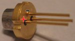
Guys (and gals) here is the pin out info for the GB diodes...I thought there was a thread on here about it -
* <---------Negative leg (grounded to the case)
Positive leg------->* * <------PD - no connection, to be safe, cut this leg 2mm from base....
Now, the above CRUDE diagram shows the diode, pins facing you, with the grounded pin (the one that looks like it is part of the housing) facing up - and the other two legs (with the little black circle around them at the base) are facing down")
* <---------Negative leg (grounded to the case)
Positive leg------->* * <------PD - no connection, to be safe, cut this leg 2mm from base....
Now, the above CRUDE diagram shows the diode, pins facing you, with the grounded pin (the one that looks like it is part of the housing) facing up - and the other two legs (with the little black circle around them at the base) are facing down