Hello all,
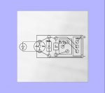
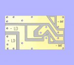
I'm going to etch a driver board on my CnC today. I was wondering if anyone has
a layout in a dxf or eps format. I can make one up but if one was already available.
I'll use Daedal's circuit, if it turns out maybe I'm willing to distribute these out to those who might want some. If anybody would like to help out on this venture it would greatly be appreciated.
I have not done this on my cnc before but i have milled some pretty small stuff. And I do have the right tooling. So it should be possible.
I was thinking of a design that would make it simple for any DIY'er to solder so thru hole seems to be the most simple.
I'm not sure what style VR would be the best to keep it small, but Radio Shack component's would be the easiest to obtain.
I'm also not sure about the boards size, I would like to shoot for 12mm wide by 25 mm long.
I don't have the dims on all the component's yet so I'm not sure if thats possible.
I welcome any commits or suggestions, is it something anybody might be interested in?
I know I'm a noobe here but I would like to be able to contribute in some way.
Thanks for reading
Chuck