Welcome to Laser Pointer Forums - discuss green laser pointers, blue laser pointers, and all types of lasers

LPF Donation via Stripe | LPF Donation - Other Methods

Links below open in new window

ArcticMyst Security by Avery

Erdabyz's switching laser drivers

D

Deleted member 8382

Guest
I've talked with him via MSN many times and I can do nothing else but tell you that he is a genius with electronics, and that he is telling me about this project since long ago, I hope everyhing works out, GL mate :)


Joined
Sep 20, 2008
Messages
17,622
Points
113
Hey erdabyz...
where are you at the development stage...
have you started to produce some sample PCB for us ???:yh:

Jerry
 
Joined
May 4, 2009
Messages
470
Points
28
Great Job so far!

Any plans on making a driver that will work we 6 and 8X Blu-Ray?

Thanks,

Ryan
 
Joined
Jun 19, 2009
Messages
2,710
Points
0
Actually, I think I need 2. Can't wait to see how these turn out. Good luck.

-Proto
 
Joined
May 4, 2009
Messages
5,443
Points
113
please I would like to try your new driver also. so see you have plenty of people to do beta testing for you now, ya just got to order more parts and get started building WE want them NOW !!!!

Peace All Pyro... :eg:
 
Joined
Jun 30, 2008
Messages
286
Points
0
Hey guys sorry fr not having answered all this time... I was on holidays and all that stuff....

As I promised here's the schematic/PCB design/parts list for the driver described in this post.

Parts list:
FOR SINGLE LI-ION CELL WITH BUILT-IN BATTERY PROTECTOR:

-1x MAX1723EZK+ ---> sample it here Ordering Info - MAX1722, MAX1723, MAX1724 1.5µA IQ, Step-Up DC-DC Converters in Thin SOT23-5
-1X TPS3808G33 ---> sample here Power Management - Supervisory Circuits(Voltage Supervisors) - TPS3808G33 - TI.com
-2X 10uF 0805 X5R capacitors. No samples for these ones, I have like 15 in stock, if you REALLY need some I can send you two for $3 + shipping
-1X 12 ohm 1/4W 0805 resistor (that's the current sensing resistor, i'll explain later how to calculate the value for higher or lower current)
-1X 10uH SMD inductor. I use these ones that you can sample: Free sample request(there are smaller ones but these were the first ones I found)
-1X 10Kohm 0805 resistor

FOR THE 1.5V AAA VERSION (NOT GUARANTEED TO WORK WITH 1.2V RECHARGEABLE CELLS):

-1x MAX1723EZK+ ---> sample it here Analog, Linear, and Mixed-Signal Devices from Maxim/Dallas Semiconductor
-2X 10uF 0805 X5R capacitors. No samples for these ones, I have like 15 in stock, if you REALLY need some I can send you two for $3 + shipping
-1X 12 ohm 1/4W 0805 resistor (that's the current sensing resistor, i'll explain later how to calculate the value for higher or lower current)
-1X 10uH SMD inductor. I use these ones that you can sample: Free sample request are smaller ones but these were the first ones I found)
-1X MBR0530 Schottky diode in SOD-123 package. Again, no samples. I have like 40 of these, if you want one it's $1 + shipping

Schematics:
These are done with paint from a schematic found in MAX1723 datasheet:

FOR LI-ION VERSION:
drivera.jpg

FOR 1.5V version:
driverbf.jpg


PCB DESIGNS:
drivera.pcb is for the li-ion version. 2 layers PCB.
driverb.pcb is for the 1.5V version, 1 layer 0,8mm PCB, solid diode mounting system. Be careful not to make solder bridges and solder the case pin FIRST. When you test that it's firmly attached, solder both + and - pins through the holes. 0,5mm tip soldering iron required. Case pin provides negative contact.

I have yet another PCB design, as small as driverb but for LI-ION version. It's the one you can see in the second set of pictures i posted. I'll upload it later as for some reason i can't find it in this computer... (i thin i overwrote it, but I have a copy on the other computer)

Soldering paste and hot air gun is recommended for soldering both drivers.
Feel free to modify them in any way, although they are very compact and the layout has been carefully made following manufacturers recomendations to avoid electrical noise problems.

designs are attached.

HOW TO SET THE CURRENT:

With a 12ohm resistor this driver will give you 100mA. If you want more or less, up to 150mA, use this formula:

Resistor value (in ohms) = 1,235/Current in Amps

For example, for 150mA you would require a 8,2 ohm resistor


HOW THIS DRIVER WORKS:

It's easy: the switching IC is designed to provide constant voltage. it has a feedback pin whith a fixed voltage, in this case 1,235V, used to chek the output voltage.
According to ohm's law, voltage drop in a resistor depends on the current that goes through them. So, when the current through the diode passes through the sensing resistor, it makes a voltage drop... that will be exactly 1,235 V... and if not, the IC will try to stabilize it... and the unic way it has is to vary the current to a value that, passing through the sensing resistor, would make a 1,235V voltage drop.

The battery protection feature uses a voltage supervisor IC, that detects if the voltage drops below 3,07V (3.7V li-ion cells shound't be discharged below 3V) and 20 milliseconds later pulls its reset line to ground. So, we connect the reset line of the supervisor to the shutdown line of the switching driver. If the shutdown pin of the driver is grounded (low state) the driver shuts down, drawing just a few uAmps from the battery. There are more TPS38G08 series IC designed for other voltages.


I found another interesting current driver IC at Texas Instruments that would allow for electronically programmed current (rather than turning a pot) and PWM dimming and all stuff like that. It would require a microcontroller and their features would "depend" on its program. It would allow up to 1200mA at 5.5V. No more than 5.5V as it's a constant current driver circuit designed for white LED's. It would also require isolated casing as there won't be common gruond or common positive. The PCB is designed but as always.... no time for further developing as I'm on holidays having as much fun as I can until university starts. I think that from now on i'll just release all the work i do for free under creative commons non commercial license.
 

Attachments

  • designs.zip
    9.7 KB · Views: 85
Last edited:
Joined
Jun 30, 2008
Messages
286
Points
0
Very good Erdabyz. I'm also using a max ic, the max711 check it out here QuickView - MAX710, MAX711 3.3V/5V or Adjustable, Step-Up Step-Down DC-DC Converters . I will sample this one, thanks for the link. I like yours too, it's more cost effective at <$2 per IC.


Yeah, that one is fine but... big and with some functions not required for this kind of drivers, that also difficult the design.

If you want to make something that works exactly like my driver but capable of more current, check Linear Technology - Linear Home Page.
For example, LT1930 is a good IC that is small and handles way more current than the MAX1723. But... the pins are assigned in the package so that you require dual layer PCB and some vias. it's not as design-friendly as MAX1723.

I mean, I choose the 1723 because it is in the perfect current range for driving a PHR, it's in SOT-23 package with a very design-friendly pin layout that allows for quick PCB designs in single layer PCB, and it had no extra unnecesary features. It is a driver designed just for PHR and similar diodes, and it works perfectly with them.
 
Last edited:
Joined
May 10, 2009
Messages
379
Points
28
Thanks for that info and link, I appreciate it. Yes, I agree it's not the easiest to build. I will defiantly try your recommendations, thanks!
 
Joined
Jun 30, 2008
Messages
286
Points
0
Thanks for that info and link, I appreciate it. Yes, I agree it's not the easiest to build. I will defiantly try your recommendations, thanks!

I was just designing a PCB for the LT1930 and i'm almost done. I think i made a mistake last time I wanted to design a PCB for it, as this time i found no problems... strange... I'll probably make one LT1930 driver tomorrow as i have 2 of them. The advantage with LINEAR products is that they give free spice software for their products so you can simulate and evaluate its performance before building the driver.
 
Joined
Jun 30, 2008
Messages
286
Points
0
I like that 1930 also, wide range is nice. I also have two LTC3529's I've been waiting to test but their so small, it will be a challenge. What do you think about the potential of the 3529 as a useable drive component erdabyz?

link: Linear Technology - LTC3529 - 1.5A, 1.5MHz Step-Up DC/DC Converter in 2mm × 3mm DFN

Fixed 5V Output---> that means unusable for our pourpose.

But check this one:
Linear Technology - LTC3454 - 1A Synchronous Buck-Boost High Current LED Driver


LED driver IC's are actually better as they are designed as constant current drivers by themselfs, so better features are available. For example you can set hugh currents using low power potentiometers, not requiring amplifiers or things like that to avoid using a big current sensing resistor, which is a problem with step-up IC's designed to provide constant voltage. However, they tend to be limited to 5.5V or so and they require isolated cases because there's no common gruound/positive pin. They are also not very design-friendly, requiring vias and double-sided PCB's.

To handle such small packages you need soldering paste and hot air. I soldered some LGA accelerometers using common soldering wire and a stove some time ago, but it's way better with hot air :D
 
Last edited:
Joined
May 10, 2009
Messages
379
Points
28
Thanks again, great info! Advice taken, I'll be looking forward to future discussions on this subject.:thanks:
 

HIMNL9

0
Joined
May 26, 2009
Messages
5,318
Points
0
Other than with your one (btw, good idea to use a power manager for the lithium version shutdown, anyway you can also use a G30, cause the undervoltage limit for rechargeable LI cells is 2,7V), i was experimenting also with other units ..... not too much free time, but found also LT1073 from linear, that have an Ilim pin (current limitation) ..... can be useful, if really works (need to get another one, anyway, i had only one and i fried it for an accident :p)

About the 1723, the trick to use the FB as current sense, instead voltage sense, don't give you any instability ? ..... and, being max 5,5V and 150mA, probably can't be used for BR like 6X or 8X

Anyway, the more problematic thing, imho, using this system, is that you need to use resistors too high in value, and the dissipation of power through them become high enough to cause heating and durability problems ..... mean, if for 100mA you need a 12 ohm resistor, and you are driving a red LD, that is, typically, acting as a 15 ohm resistor (in fact of power dissipation, ofcourse), you have almost the same power of the diode dissipated from the resistor ..... this at least is one of the problems i still can't solve in my tests, not without use at least an op amp or a transistor (trying to keep the driver the less possible components, but perhaps that, when you need it, you need it :p)

Also, MC34063 from ST works good and have current limitation, but require bigger coils, typical 150 to 220 uH, to work stable, at least in my prototypes, and find these coils in sizes that fit aixiz module space is not easy.

LM2621 from National is a good one, too, can go from 1,5V to 12V (at least, these are the values i got in tests) ..... a bit more complex in design, but the fact that power ground is separated from signal ground, give me the idea that it can be turned in a current regulated driver, putting a resistor between the power ground pin and the negative, and using it for current sense circuit.

Never got any decent result with TPS5410, it require too much external circuitry for do a decent current regulation (op amps and so on, you know)

TPS61040 only give 380mA, and 63010 can give some good results, but with that damn 20-pins micropackage, is a pain you-know-where, also just experimenting, and for sure is not in the possibility of the most part of the hobbysts (also just for make some tests, i needed to transform it in a spider, soldering little wires on the chip, damn designers :p)

Someone got some decent results, with any of these ones ?
 
Joined
Jun 30, 2008
Messages
286
Points
0
Other than with your one (btw, good idea to use a power manager for the lithium version shutdown, anyway you can also use a G30, cause the undervoltage limit for rechargeable LI cells is 2,7V), i was experimenting also with other units ..... not too much free time, but found also LT1073 from linear, that have an Ilim pin (current limitation) ..... can be useful, if really works (need to get another one, anyway, i had only one and i fried it for an accident :p)

About the 1723, the trick to use the FB as current sense, instead voltage sense, don't give you any instability ? ..... and, being max 5,5V and 150mA, probably can't be used for BR like 6X or 8X

Anyway, the more problematic thing, imho, using this system, is that you need to use resistors too high in value, and the dissipation of power through them become high enough to cause heating and durability problems ..... mean, if for 100mA you need a 12 ohm resistor, and you are driving a red LD, that is, typically, acting as a 15 ohm resistor (in fact of power dissipation, ofcourse), you have almost the same power of the diode dissipated from the resistor ..... this at least is one of the problems i still can't solve in my tests, not without use at least an op amp or a transistor (trying to keep the driver the less possible components, but perhaps that, when you need it, you need it :p)

Also, MC34063 from ST works good and have current limitation, but require bigger coils, typical 150 to 220 uH, to work stable, at least in my prototypes, and find these coils in sizes that fit aixiz module space is not easy.

LM2621 from National is a good one, too, can go from 1,5V to 12V (at least, these are the values i got in tests) ..... a bit more complex in design, but the fact that power ground is separated from signal ground, give me the idea that it can be turned in a current regulated driver, putting a resistor between the power ground pin and the negative, and using it for current sense circuit.

Never got any decent result with TPS5410, it require too much external circuitry for do a decent current regulation (op amps and so on, you know)

TPS61040 only give 380mA, and 63010 can give some good results, but with that damn 20-pins micropackage, is a pain you-know-where, also just experimenting, and for sure is not in the possibility of the most part of the hobbysts (also just for make some tests, i needed to transform it in a spider, soldering little wires on the chip, damn designers :p)

Someone got some decent results, with any of these ones ?

No, first I thought that it could be unstable or that it wouldn't work with the resistor trick, but then I started making simulations and for my surprise, everything was working OK and stable. It's also fine in the real product, I did a 5 minutes run test through my test load and it was steady at a bit more than 100mA.

The power dissipated in the resistor will always be, at 100mA, (0,100)^2*12=0,12W or what is the same, 120mW. So, a 1/4 watt resistor works fine for this, and it can perfectly withstand that power dissipation.

As i told you before this one is designed just for PHR diodes and other similar blu-rays, not for 8x's or 6x's. For those higher current diodes the resistor trick still works but it would be better to use a small value current sensing resistor and an amplifier with a potentiometer as voltage divider os something like that to get the same effect without wasting power in a resistor.
 

HIMNL9

0
Joined
May 26, 2009
Messages
5,318
Points
0
Just as suggestion.

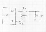
If you want to try this, you can use a transistor (a common SI PNP, or if you can get it, a GE PNP, that is better)

This way, you have to manage with 0,6V, in case of a SI transistor, or also better with 0,25V, using a GE transistor, so the resistor can be at least half the value, and also almost 6 times less, in case of the GE one.

Basically, is the most old limiter circuit i know ..... when the voltage at the RX is at least 0,6V (or 0,2V), the transistor start to conduct, and this increase the voltage at FB pin, that for keep it at 1,25V, must decrease the output voltage.

Only advantge than in your config, is that you can use lower resistor, and dissipate less power, but this without use an op amp ..... ofcourse, with an op amp and a division network, it's all more precise, but this way just need to add a transistor and a resistor (and maybe also just the transistor, cause i added the resistor for safety only :D).

I used a 2SA1015, and got a 122ma limiter with 4,7 ohm, but just cause i had it in a tire ..... can be used probably any type of PNP transistor ..... the only problem that i see, actually, can be find a PNP GE transistor in a SOT23 or similar SMD package, maybe :p


Edit: btw, what do you use for simulations ? ..... i have to admit that i'm an "old-type" electronic experimenter ..... draw a circuit, stuck the parts together, and see if works or if smokes (LOL)
 

Attachments

  • 1723mod.jpg
    1723mod.jpg
    159.2 KB · Views: 627
Last edited:


Top