Welcome to Laser Pointer Forums - discuss green laser pointers, blue laser pointers, and all types of lasers

LPF Donation via Stripe | LPF Donation - Other Methods

Links below open in new window

ArcticMyst Security by Avery

DIY Thermal LPM for under $50

djQUAN

0
Joined
May 27, 2013
Messages
1,154
Points
63
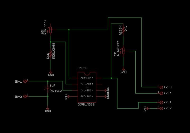
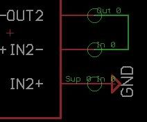
I think you mixed up IN- and OUT-.

Otherwise, looks good. You can actually get rid of R2 and just short the pins together.

If it were me though, I would just connect the R4 output to the second op amp and take OUT- from the op amp output :)


Joined
Jan 4, 2012
Messages
69
Points
0
LPMschem.jpg


opampwrong.jpg

+ 6. and 7. Between 1K resistor.

JiCFxl.png


I thik this is good! :) please check it!
 
Last edited:

honeyx

0
Joined
Jun 12, 2011
Messages
377
Points
28
In this picture please write me OpAmp (ic2 lm358)
Used pins... because here is dont writed :

1957Fig01.gif

Is this that hard to understand?

You see in your other pic which pin is +In for the unused OpAmp. It´s Pin no. 5. You only need a voltage divider build by two resistors. Both can be either 1K or 5K or even 10K. Doesn´t matter. It only matters the +In gets half the voltage you feed the IC with.

The shematics is really simple: one resistor between VDD and pin 5 and the other one between pin 5 and VSS plus pin 6 and 7 bridged. So this costs you only two extra resistors to terminate the OpAmp correctly.
 

honeyx

0
Joined
Jun 12, 2011
Messages
377
Points
28
For the first one you need a DC/DC converter to feed it separately and make it work correctly. Or two separate batteries. If the secound one is using the same type of chip, this will be also necessary but there I´m also not sure it has a 0.001 resolution.

Most cheap LCD panels sold on ebay are lusing the same type of chipset like the first one you posted and need a separate power source. And most LED panels sold there do only have a 0.01 resolution.

The only exeption I found is the one I posted you. This one can be feeded by the same battery, has a 0.001 resolution and can be used up to 30V, so theoretically measure up to 30W. With this one you do not have to deal with DC/DC converters, bridging pads to move the decimal point and to exchange resistors to change to voltage range.

Only disadvantage is, it has no separate "-" in. But this is not really that important.

So better order the one I suggested you and use the other two for something else.
 
Joined
Jan 4, 2012
Messages
69
Points
0
I ordered this item!Thanks for advise! If I dont have on this voltmeter " - in " , is it enough to connect only from PCB " voltmeter out + " ? I think that the " - in " will be from power supply! what do you think?


For the first one you need a DC/DC converter to feed it separately and make it work correctly. Or two separate batteries. If the secound one is using the same type of chip, this will be also necessary but there I´m also not sure it has a 0.001 resolution.

Most cheap LCD panels sold on ebay are lusing the same type of chipset like the first one you posted and need a separate power source. And most LED panels sold there do only have a 0.01 resolution.

The only exeption I found is the one I posted you. This one can be feeded by the same battery, has a 0.001 resolution and can be used up to 30V, so theoretically measure up to 30W. With this one you do not have to deal with DC/DC converters, bridging pads to move the decimal point and to exchange resistors to change to voltage range.

Only disadvantage is, it has no separate "-" in. But this is not really that important.

So better order the one I suggested you and use the other two for something else.
 
Last edited:

honeyx

0
Joined
Jun 12, 2011
Messages
377
Points
28
I ordered this item!Thanks for advise! If I dont have on this voltmeter " - in " , is it enough to connect only from PCB " voltmeter out + " ? I think that the " - in " will be from power supply! what do you think?

Yes, that is what I finally did with this voltmeter, so the secound pot for trimming the "-out" isn´t in use though it´s still there on the pcb.

However this voltmeter is doing quite a good job in zeroing, so I´m getting something between 0.000 and 0.001 when no laser is shining on the TEC.

The "-out" is so to say left to connect a DMM when in need.
 

honeyx

0
Joined
Jun 12, 2011
Messages
377
Points
28
thx!

I ordered this TEC : Module Thermoelectric Tecnologic Power Generator Tec 6 6mm x 8 3mm Laird Compay | eBay


Zeebit wrote: Vmax is 2.7V.
Others ( MarioMaster ) are writing that it will be working 99%! What do you think?

I already answered somwhere in this topic that this TEC will be fine. It has 6x6 junctions exactly like the TEC I used for my first LPM where the output is more linear compared to the other TEC with 7x7 junctions I´m using in another LPM.

So nothing to worry about the TEC. I also ordered two of them :)
 

hozone

0
Joined
Nov 24, 2013
Messages
27
Points
0
hello all,
i'm building this LPM too, but i'm a neebie in laser power metering, so i ask you:

1)
could you confirm me that the attached schematics is correct?
5k resistor will be 4k7 1/4w 5%
5k trimmer is not multiturn
10k trimmer is multiturn

2)
power supply will be 5v (or other)?

3)
also, are those components correct?
i've buy this TEC
TEC 6.6mm X 8.3mm Laird Compay
and this LCD meter
5 Digit DC 0-33.000V Digital Voltmeter

4)
is this pain right?
to paint the TEC i will you a black paint for motor (that resist heat).


thank you for your help!
 

Attachments

  • LPMschem.jpg
    LPMschem.jpg
    26.3 KB · Views: 213


Top