Welcome to Laser Pointer Forums - discuss green laser pointers, blue laser pointers, and all types of lasers

LPF Donation via Stripe | LPF Donation - Other Methods

Links below open in new window

ArcticMyst Security by Avery

DIY Thermal LPM for under $50

Joined
Jan 14, 2011
Messages
3,816
Points
63
In fact, I actually did clean it a while back. That was a photo from the before part of the cleaning process. Here is the current state of the diode (there is still an artifact, but it's actually not that bad).

P6050140.jpg


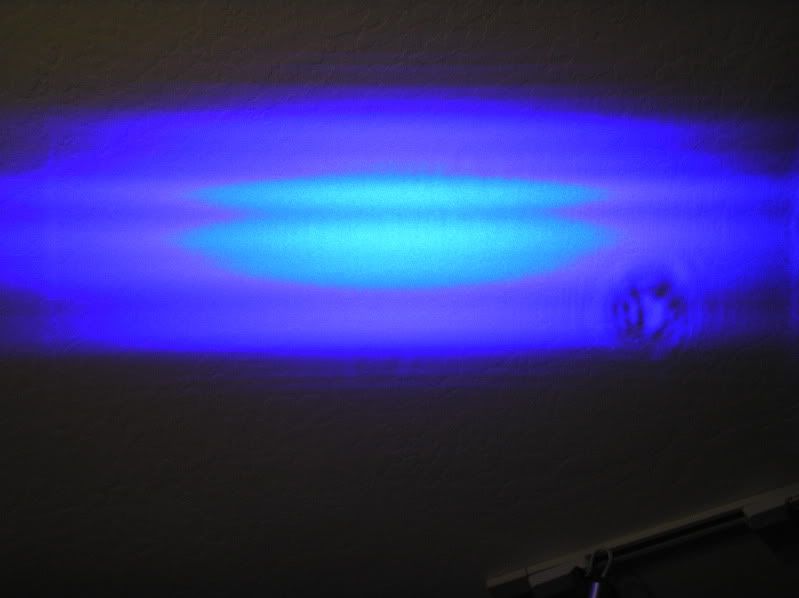
EDIT: And that artifact looks a lot less... mangled... in person than it does in the picture.
 
Last edited:


Joined
May 25, 2010
Messages
3,655
Points
0
:gj: I could not pull that off.;)

You must of caught it right away. But i still think that could be why your diode is not putting out as much.
 
Joined
Jan 14, 2011
Messages
3,816
Points
63
Hmm. And is it just me or are there less "lines" in that photo than there are in the previous one?
 
Joined
Sep 20, 2008
Messages
17,622
Points
113
Yeah... and one of the photos is upside down...
Maybe it is just out of focus....
If not there are some emitters that are no longer emitting...


Jerry

You can contact us at any time on our Website: J.BAUER Electronics
 
Last edited:
Joined
Apr 23, 2011
Messages
212
Points
0
It took me a sec to decipher your guys circuit diagram. Finally redrew it. Might already be a simple version like this somewhere. Anyhow, thats a super cool way of applying offset with a single supply. Never thought of that before. Not sure I see the point of 100nf cap though. No reason to put a bypass cap on a sensory input. However, I would highly recommend adding a low frequency RC filter onto that input to reduce the noise.

circuitw.png
 
Joined
Sep 20, 2008
Messages
17,622
Points
113
It took me a sec to decipher your guys circuit diagram. Finally redrew it. Might already be a simple version like this somewhere. Anyhow, thats a super cool way of applying offset with a single supply. Never thought of that before. Not sure I see the point of 100nf cap though. No reason to put a bypass cap on a sensory input. However, I would highly recommend adding a low frequency RC filter onto that input to reduce the noise.

circuitw.png

The cap is to reduce the input noise if the sensor is far
from the amplifier or the wire used between the Sensor
and amplifier is not properly shielded...

The only problem with the Offset control is that it can not
go below 0vdc which is required when the heatsink of the
sensor starts to get warm from repeated Laser tests on the
sensor side.. Which is the problem with the Alpha LPM..


Jerry

You can contact us at any time on our Website: J.BAUER Electronics
 
Last edited:
Joined
Mar 26, 2010
Messages
3,220
Points
0
The solution for this is to use a negative voltage dc-dc converter and actually use dual rails.. This doesn't incur much extra cost since your not dealing with a lot of current, and low power monolithic -V sources are cheap. Though going that route, you can do away with the whole bias adjustment section on the the negative output side, and use an opamp that has a bias adjustment pin like a 741.
 
Joined
Sep 20, 2008
Messages
17,622
Points
113
I agree that it would solve the Zero problem...

But you need to be careful using DC/DC converters since
the inexpensive ones tend to produce quite a bit if ripple..
Good filtering would be a must..

We saw that with all the problems with the Kenometer
Lites and other similar built LPMs that used the OPHIR
heads and DC/DC poorly filtered converters...


Jerry

You can contact us at any time on our Website: J.BAUER Electronics
 
Last edited:
Joined
Apr 23, 2011
Messages
212
Points
0
The only problem with the Offset control is that it can not
go below 0vdc which is required when the heatsink of the
sensor starts to get warm from repeated Laser tests on the
sensor side.. Which is the problem with the Alpha LPM..
Jerry

Wait... how is that correct? Shouldn't it work? Say you call the top output node V1 and the bottom output node V2. Using the pot you can set V2 to .1V. Then V1 would have to surpass .1V in order for the output, (V1 -V2) >0. So yea, it should zero just fine? Just not in the case if your feeding it to a micro input. However, if its a volt meter display, it should work fine. What am i missing? All the volt meter display will take is V1-V2. It doesn't calculate its output with respect to ground.

Pic for less confusion:
zarg.png
 
Last edited:
Joined
Mar 26, 2010
Messages
3,220
Points
0
I agree that it would solve the Zero problem...

But you need to be careful using DC/DC converters since
the inexpensive ones tend to produce quite a bit if ripple..
Good filtering would be a must..

We saw that with all the problems with the Kenometer
Lites and other similar built LPMs that used the OPHIR
heads and DC/DC poorly filtered converters...


Jerry


I just think it's amazing that your LPM's are the only ones you don't find flaws with. :whistle: ;)
 
Last edited:
Joined
Sep 20, 2008
Messages
17,622
Points
113
I just think it's amazing that your LPM's are the only ones you don't find flaws with. :whistle: ;)
You're the one that brought up DC/DC converters to use with
a Laser Power Meter Circuit...

I'm stating facts as we know them through datasheets and our
own R&D...

We don't use any DC/DC conveters on the LaserBee products
except for the Limited Edition 5Watt LaserBee that uses the
OPHIR head... that requires a split +/- PS.
We uses good filtering on the DC/DC converter we used to
eliminate the reading wandering...

I'm sorry if these facts and information annoys you...
Just don't read what I post..:D

BTW did you find some flaws with you LaserBee... We would
really like to know so that we can make a better product...
Any useful input would be appreciated....:beer:


Jerry

You can contact us at any time on our Website: J.BAUER Electronics
 
Last edited:
Joined
Aug 13, 2011
Messages
80
Points
0
I couldn't find a proper schematic either and based on the fact that the data in the brd file suggests different parts were originally intended and later renamed I am wondering if there never was a schematic. (.sch)

So, I reverse-engineered one that is consistent with the brd file allowing forward-back annotation to work. (Change one, other is updated.)

You can find the image and zip of the brd/sch attached so they won't get lost in time...
 

Attachments

  • easylpm_1.2.9_derived.zip
    20 KB · Views: 60
  • easylpm_1.2.9_drived.png
    easylpm_1.2.9_drived.png
    8.9 KB · Views: 271
Last edited:
Joined
Aug 13, 2011
Messages
80
Points
0
I couldn't help myself and cleaned it up a bit on the pcb.

I also added a quick noise-reduction for the secondary opamp in the IC.
It really shouldn't have floating inputs so I made it a follower and grounded the input.
 

Attachments

  • easylpm_1.2.9_mod_1.zip
    20.3 KB · Views: 61
  • easylpm_1.2.9_mod_1_pcb.png
    easylpm_1.2.9_mod_1_pcb.png
    27.9 KB · Views: 293
  • easylpm_1.2.9_mod_1_sch.png
    easylpm_1.2.9_mod_1_sch.png
    10.8 KB · Views: 1,292
Joined
Mar 26, 2010
Messages
3,220
Points
0
Making the second opamp not float has already been discussed thoroughly in the text in this thread. But no one has drawn up a schematic or board layout for it until you did though.

Though to be honest. Your schematics are confusing the hell out of me. There was nothing wrong with the previously posted schematics except for the second opamp not being terminated properly.
 
Last edited:


Top