- Joined
- Sep 20, 2008
- Messages
- 17,622
- Points
- 113
I actually built one of these about 2 months ago, but I failed. I gave up because I am waiting for summer break so I can figure out what went wrong.
I used MarioMaster's and Jib's schematics but the readings seem to fluctuate a lot. It worked for a moment and I went eat dinner came back and it didn't work :undecided:
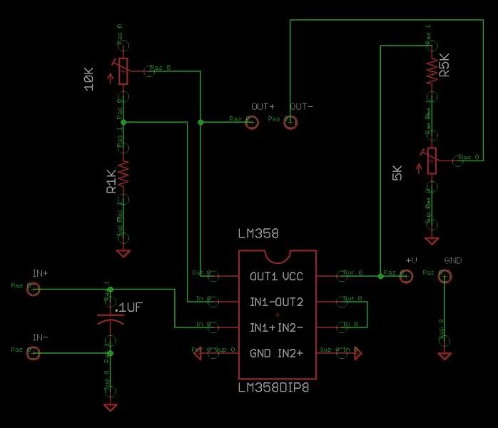
Schematic:
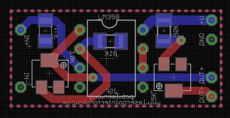
Board:
The reason your circuit is not working is that you have made
a one wring connection.
The connection on your Schematic and your Artwork between
pins 6 and 7 should be removed and put between pins 6 and 5...
BTW... the industry standard for PCB layout colors is Blue for
the component side (top) and red for the solder side (bottom)..
Jerry
You can contact us at any time on our Website: J.BAUER Electronics
Last edited: