LPF Donation via Stripe | LPF Donation - Other Methods
Links below open in new window
ArcticMyst Security by Avery


You are using an out of date browser. It may not display this or other websites correctly.
You should upgrade or use an alternative browser.
You should upgrade or use an alternative browser.
DIY Laser Torch
- Thread starter Daedal
- Start date


Gazoo
0
- Joined
- Jun 9, 2007
- Messages
- 3,206
- Points
- 38
I received my goggles within a couple of days from the time I placed my order. I was surprised how fast they came.
Gazoo
0
- Joined
- Jun 9, 2007
- Messages
- 3,206
- Points
- 38
If you have your meter on the 10AMP scale reading, then it will show .25ma's. This is the same as 250ma's.
Gazoo said:If you have your meter on the 10AMP scale reading, then it will show .25ma's. This is the same as 250ma's.
This is how my meter is. So how can I get it to say 245-250ma like my previous pics? Something is up here.


Gazoo
0
- Joined
- Jun 9, 2007
- Messages
- 3,206
- Points
- 38
Well I really don't know...you have an autoranging meter and it looks like you have it all set up like you did before. I don't know why it reads .25ma's. Sorry.
Gazoo said:Well I really don't know...you have an autoranging meter and it looks like you have it all set up like you did before. I don't know why it reads .25ma's. Sorry.
Maybe it's fried somewhere inside?
If you are using the meter in current mode in series with your battery, do not use the mA mode, use the 20A mode (with the probe plugged into the proper location). The mA mode introduces a larger resistance in the circuit and will cause the driver to drop out more quickly.
Note: when you insert the DMM in the circuit, you are affecting operating parameters of the circuit. A better way to measure the current going to the LD is to measure the voltage drop across the resistors between Vout and Vadj. Since you know the value of the resistors, you can calculate the current using: I = V/R
Why do it this way? The DMM has a very high impedance when measuring voltage. (Translation: it draws essentially no current and therefore does not affect the operation of the circuit)
For clarification purposes:
these components will only have a slight affect on the circuit during transients (milli/micro-seconds when switching on and off). The diode is reversed biased so no current will be flowing and the capacitor, once charged, will act as a open circuit to DC current.
In this case, we are only concerned about steady-state operation (except for LD protection) so you can ignore those components when considering the LD current.
roSSco said:The diode and cap are in PARALELL to the LD. If you think those items have NO EFFECT on the current that gets to the LD, you are mistaken.
I'll ask again: Do you want an estimate of the current going to the LD, or do you want to know exactly how much current is going through the diode?
knimrod, while many of the things you say above are true, they do not apply to the situation at hand.
knimrod
0
- Joined
- Nov 4, 2007
- Messages
- 385
- Points
- 0
chimo said:If you are using the meter in current mode in series with your battery, do not use the mA mode, use the 20A mode (with the probe plugged into the proper location). The mA mode introduces a larger resistance in the circuit and will cause the driver to drop out more quickly.
Note: when you insert the DMM in the circuit, you are affecting operating parameters of the circuit. A better way to measure the current going to the LD is to measure the voltage drop across the resistors between Vout and Vadj. Since you know the value of the resistors, you can calculate the current using: I = V/R
Why do it this way? The DMM has a very high impedance when measuring voltage. (Translation: it draws essentially no current and therefore does not affect the operation of the circuit)
There wouldn't be much point in measuring the voltage between Vout and Vadj since it's always ~1.25 volts while in regulation. So that wouldn't be a very good way to actually measure the current.
knimrod said:[quote author=chimo link=1186966870/240#248 date=1200262825]If you are using the meter in current mode in series with your battery, do not use the mA mode, use the 20A mode (with the probe plugged into the proper location). The mA mode introduces a larger resistance in the circuit and will cause the driver to drop out more quickly.
Note: when you insert the DMM in the circuit, you are affecting operating parameters of the circuit. A better way to measure the current going to the LD is to measure the voltage drop across the resistors between Vout and Vadj. Since you know the value of the resistors, you can calculate the current using: I = V/R
Why do it this way? The DMM has a very high impedance when measuring voltage. (Translation: it draws essentially no current and therefore does not affect the operation of the circuit)
There wouldn't be much point in measuring the voltage between Vout and Vadj since it's always ~1.25 volts while in regulation. So that wouldn't be a very good way to actually measure the current.[/quote]
I beg to differ. That is the BEST way to measure the current (unless one is incapable of doing the math). Ideally, you would measure the resistors to get a precise resistance (be sure to subtract the DMM lead resistance - probably less than an ohm).
The current sink into the Adj pin is in the order of 50uA (microAmps. 1mA =1000uA) so for most cases it can be ignored. Now, where does the rest of the current go? - you guessed it to the LD.
As you have noted, the voltage drop between Vout and Vadj is NOT always 1.25V. There are many times when folks here have not supplied the driver with a sufficient voltage overhead. In addition, when these poeple use their DMMs in voltage measuring mode, they are less apt to cause a short by forgetting to change from current mode to voltage mode.
Now, if you do not have access to the sense resistors, by all means use the DMM in current more (10 or 20A scale) on the battery side of the driver.
knimrod
0
- Joined
- Nov 4, 2007
- Messages
- 385
- Points
- 0
chimo said:[quote author=knimrod link=1186966870/240#250 date=1200268609][quote author=chimo link=1186966870/240#248 date=1200262825]If you are using the meter in current mode in series with your battery, do not use the mA mode, use the 20A mode (with the probe plugged into the proper location). The mA mode introduces a larger resistance in the circuit and will cause the driver to drop out more quickly.
Note: when you insert the DMM in the circuit, you are affecting operating parameters of the circuit. A better way to measure the current going to the LD is to measure the voltage drop across the resistors between Vout and Vadj. Since you know the value of the resistors, you can calculate the current using: I = V/R
Why do it this way? The DMM has a very high impedance when measuring voltage. (Translation: it draws essentially no current and therefore does not affect the operation of the circuit)
There wouldn't be much point in measuring the voltage between Vout and Vadj since it's always ~1.25 volts while in regulation. So that wouldn't be a very good way to actually measure the current.[/quote]
I beg to differ. That is the BEST way to measure the current (unless one is incapable of doing the math). Ideally, you would measure the resistors to get a precise resistance (be sure to subtract the DMM lead resistance - probably less than an ohm).
The current sink into the Adj pin is in the order of 50uA (microAmps. 1mA =1000uA) so for most cases it can be ignored. Now, where does the rest of the current go? - you guessed it to the LD.
As you have noted, the voltage drop between Vout and Vadj is NOT always 1.25V. There are many times when folks here have not supplied the driver with a sufficient voltage overhead. In addition, when these poeple use their DMMs in voltage measuring mode, they are less apt to cause a short by forgetting to change from current mode to voltage mode.
Now, if you do not have access to the sense resistors, by all means use the DMM in current more (10 or 20A scale) on the battery side of the driver.[/quote]
IMHO: You are not measuring the current to the laser diode by measuring the voltage across the Vout and Vadj pins. You are measuring the LM317's reference voltage which is spec'ed at 1.20-1.30 volts. The math would have been done when the resistor was selected. Yes, there is something wrong if the voltage is anything other than 1.2-1.3 volts and yes, assuming the resistor is (still) at the intended value, the math will still come out right. But I maintain it's not a good way to measure the current, especially when you have a DMM capable of measuring current. Lastly, a slip when putting meter probes on the LM317 pins could easily kill the LD.
So I guess we'll have to agree to diasagree...
")
knimrod said:[quote author=chimo link=1186966870/240#251 date=1200270055][quote author=knimrod link=1186966870/240#250 date=1200268609][quote author=chimo link=1186966870/240#248 date=1200262825]If you are using the meter in current mode in series with your battery, do not use the mA mode, use the 20A mode (with the probe plugged into the proper location). The mA mode introduces a larger resistance in the circuit and will cause the driver to drop out more quickly.
Note: when you insert the DMM in the circuit, you are affecting operating parameters of the circuit. A better way to measure the current going to the LD is to measure the voltage drop across the resistors between Vout and Vadj. Since you know the value of the resistors, you can calculate the current using: I = V/R
Why do it this way? The DMM has a very high impedance when measuring voltage. (Translation: it draws essentially no current and therefore does not affect the operation of the circuit)
There wouldn't be much point in measuring the voltage between Vout and Vadj since it's always ~1.25 volts while in regulation. So that wouldn't be a very good way to actually measure the current.[/quote]
I beg to differ. That is the BEST way to measure the current (unless one is incapable of doing the math). Ideally, you would measure the resistors to get a precise resistance (be sure to subtract the DMM lead resistance - probably less than an ohm).
The current sink into the Adj pin is in the order of 50uA (microAmps. 1mA =1000uA) so for most cases it can be ignored. Now, where does the rest of the current go? - you guessed it to the LD.
As you have noted, the voltage drop between Vout and Vadj is NOT always 1.25V. There are many times when folks here have not supplied the driver with a sufficient voltage overhead. In addition, when these poeple use their DMMs in voltage measuring mode, they are less apt to cause a short by forgetting to change from current mode to voltage mode.
Now, if you do not have access to the sense resistors, by all means use the DMM in current more (10 or 20A scale) on the battery side of the driver.[/quote]
IMHO: You are not measuring the current to the laser diode by measuring the voltage across the Vout and Vadj pins. You are measuring the LM317's reference voltage which is spec'ed at 1.20-1.30 volts. The math would have been done when the resistor was selected. Yes, there is something wrong if the voltage is anything other than 1.2-1.3 volts and yes, assuming the resistor is (still) at the intended value, the math will still come out right. But I maintain it's not a good way to measure the current, especially when you have a DMM capable of measuring current. Lastly, a slip when putting meter probes on the LM317 pins could easily kill the LD.
So I guess we'll have to agree to diasagree...
[/quote]
I would measure the voltage at the resistor (less chance for slipping) but you do make a good point
. My concern with using the current mode is the mistake that a lot of people make by using the mA scale. That introduces a resistance (sometimes up to a few ohms when you include the DMM leads) that can affect the circuit operation due to the voltage drop across it. This can cause the driver to go out of regulation if the voltage overhead is insufficient (as we have already seen numerous times on this board).
Alternately, one could insert an R1 or an R05 resistor in the loop and use that to calculate the current.
Having said all that, I often use both methods for current measurement - it depends on how sensitive the driver is to battery voltage. What is important here is that the folks new to electroonics make the effort to understand what they are doing and how the circuit works. Sometimes the journey is more fulfilling than the destination. Cheers,
Paul
- Joined
- Oct 27, 2007
- Messages
- 320
- Points
- 0
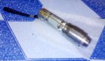
hi daedal im one of your fan using your diy regulator for LD, i built blu-ray running quite good using your LD driver, im now on going to build for the first time DIY dvd laser using LG 16x burner, about the battery is it recommended to use 4pcs LR44 to have 6v input power or something like 2pcs CR2? please help me to build this one well, thanks. i have my pic of my casing i will use to the DIY dvd laser burner, check it out.
Attachments