

knimrod
0
- Joined
- Nov 4, 2007
- Messages
- 385
- Points
- 0
This is a companion thread to the DIY Laser Power Meter thread.
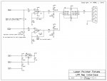
I've completed an initial design for a DIY Laser Power Meter RS-232 Interface Module and am attaching the schematic here. This module uses a PIC12F683 microcontroller. I'm using two of its 10-bit A/D inputs for two separate ranges: 0-1W with 1mW resolution, and 0-4W with 4mW resolution. The overall design is simple. The interface module accepts the output signal from the DIY LPM amp and splits it off to two separate amplifier channels. To achieve 1mW resolution on the first channel, the signal is amplified with a gain of 5. To achieve 4mW resolution on the other channel, the signal is amplified with a gain of 1.25. The microcontroller converts both outputs simultaneously and streams both ranges out the serial port. The host application will only need to pick the range it wants to monitor from the data stream. Optionally, the circuit can be configured for a single power range and a current measurement (0-1A @ 1mA res.) feature.
The Interface module can share the power supply (two 9V batteries) from the DIY Laser Power Meter. I have a PCB design completed and if there is enough interest, I'll be offering this as a kit of parts. I'll document the PCB/kit in an upcoming post.
I'm working on a simple PC application to display power and export a log. It will not be very sophisticated. Regrettably, I will not be able to release the source code for my simple application because it uses libraries that are considered proprietary. Ideally, someone else who's skilled in Visual Basic would come up with a more elaborate, open-source application for parsing the data stream and displaying/charting/logging laser power.
This particular design has not been tested and I'll need to order PCBs and parts before doing so. I'll be taking advance orders and donations to get this done. I expect a kit of parts to be about $25.00 ea., shipped.
So who's interested?


")
