knimrod
0
- Joined
- Nov 4, 2007
- Messages
- 385
- Points
- 0
Not at all... I'll PM payment info to you.


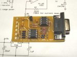
knimrod said:I've done some preliminary testing of the interface module and it appears to work perfectly.
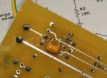
There is one problem however and that is that the output from the LPM amp is a bit noisy for an A/D process with no other filtering. The noise is only a few LSBs but I'm not happy with it. I've made a preliminary fix by soldering a .1uf cap across the amplifier feedback resistor (between pins 2 & 6 of the LTC1050) and that definetely solves the problem. I suppose I could write a software filter for the PIC and I'll have to consider that.
Also, I'm wondering if there shouldn't be some offset built into the interface to allow for a reliable zero. The PIC can't convert a negative voltage and a negative voltage is the same as 0 to the A/D converter (actually it's clamped). Because of this, it would be possible to inadvertently put some dead-band in the measurement if the offset was set below 0.
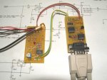
amkdeath said:do the 2 wires going to the interface module from the DPM out on the main PCB solder in parallel with the original DPM setup?
dkelley said:I would opt for the best hardware solution possible and keep the software simple. If a cap will solve a jitter problem
I would go for that. Deadband may be another problem.