Welcome to Laser Pointer Forums - discuss green laser pointers, blue laser pointers, and all types of lasers

LPF Donation via Stripe | LPF Donation - Other Methods

Links below open in new window

ArcticMyst Security by Avery

DIY Laser Power Meter

roSSco

0
Joined
Dec 5, 2007
Messages
649
Points
18
positron said:
[quote author=roSSco link=1200112201/15#20 date=1200673469][quote author=knimrod link=1200112201/15#19 date=1200665971]If those of you outside the US really want one, I'm sure we can figure out how to get it to you.

I'll buy some for those that need it overseas. ;) It's not an illegal to export item is it? ::)

Paypal me the funds for the item + shipping and I'll be happy to help.

r0ssc0i@yahoo.com[/quote]

Hey r0ssc0,

I would like to take you up on that offer, how can I find out the postage so that I know how much money to send you?

cheers.[/quote]
Where are you?


Kenom

0
Joined
May 4, 2007
Messages
5,629
Points
63
How's the progress on the pc interface knimrod? I want to buy some from ya!
 

roSSco

0
Joined
Dec 5, 2007
Messages
649
Points
18
I bought this meter and the instructions for the dip switches and wiring is confusing!
http://cgi.ebay.com/200Vdc-GREEN-LC...ryZ46412QQssPageNameZWDVWQQrdZ1QQcmdZViewItem

1zhelp.gif
 
Joined
Nov 4, 2007
Messages
385
Points
0
Kenom said:
How's the progress on the pc interface knimrod?  I want to buy some from ya!

I've got the hardware interface working to a degree but the bigger part of the job (at least for me) is the PC application software. If someone out there is willing to write the PC application software for this project, please let me know..
 
Joined
Aug 16, 2007
Messages
241
Points
0
If I could plot milliwats vs. current, or possibly vs. voltage, that'd be the most useful to me.
But of course that'd need a voltage input from the laser supply, so it wouldn't be any use to someone with a sealed unit.
Is wattage vs. time a useful plot, compared to just reading the number off the display?
What are your plans for the interface?
 
Joined
Nov 4, 2007
Messages
385
Points
0
Zarniwoop said:
If I could plot milliwats vs. current, or possibly vs. voltage, that'd be the most useful to me.
But of course that'd need a voltage input from the laser supply, so it wouldn't be any use to someone with a sealed unit.
Is wattage vs. time a useful plot, compared to just reading the number off the display?
What are your plans for the interface?

Currently, my prototype reads the voltage output from the amp and converts it to a 10-bit value (0-1023 mW) for transfer via RS-232. That's it.

I have some plans for a scaling circuit that will extend the range at the expense of some resolution. I was also considering a programmable current source that could drive an LD directly and facilitate automated testing. Adding additional inputs for voltage and current seem like a good idea too. But all this feature creep adds to the development time and cost..
 

roSSco

0
Joined
Dec 5, 2007
Messages
649
Points
18
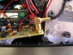
Finally got some pics. The first one shows how I used the connector that came on the board. I cut 3 legs off so it would fit on the new pcb. :cool:
 

Attachments

  • PSconn1.jpg
    PSconn1.jpg
    381.1 KB · Views: 412

roSSco

0
Joined
Dec 5, 2007
Messages
649
Points
18
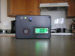
The finished product. It does zero out but jumped to .001 when I took the pic. :mad:

I used a different size case than the one in the parts list. I can't imagine cramming all of that into a smaller case!
 

Attachments

  • P1010001_002.JPG
    P1010001_002.JPG
    64.4 KB · Views: 1,485

roSSco

0
Joined
Dec 5, 2007
Messages
649
Points
18
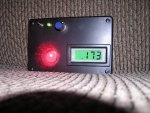
In action w/a Dorcy mini.
 

Attachments

  • PSaction1.jpg
    PSaction1.jpg
    449.9 KB · Views: 645
Joined
Oct 28, 2007
Messages
2,631
Points
48
i want to make one, but im hesitant and not to good with schematics, I dont want to screw anything up. can someone post a video of them making one? if Someone does, Ill order one of your boards
 
Joined
Oct 28, 2007
Messages
2,631
Points
48
or mabe someone can post a clear close up of the front and back of the finished and soldered GB board... im still confused how the coherent sensor attaches to the board
 

roSSco

0
Joined
Dec 5, 2007
Messages
649
Points
18
amkdeath said:
or mabe someone can post a clear close up of the front and back of the finished and soldered GB board... im still confused how the coherent sensor attaches to the board
The first post on this page shows how I connected the sensor to the board. It was a little difficult to desolder from the original board but with a desoldering iron from Radio Shak it was easy. ;)

I say go for it! If you get one of knimrod's pcbs it is labeled for all of the parts placements. There are pics of it assembled in this thread.
 
Joined
Nov 4, 2007
Messages
385
Points
0
Nice work! I am genuinely impressed.  I really like the idea of re-using that connector.  I may update the PCB to accept the connector directly.  Even if you wind up running the sensor head remotely with a seperate bulkhead BNC connector, you can still use the shielded cable from the stock connector, cutting off the BNC end.. Or better yet, get a BNC to BNC bulkhead adapter (Digi-Key #A97547-ND) and use the complete cable inside the enclosure.
 
Joined
Nov 4, 2007
Messages
385
Points
0
amkdeath said:
or mabe someone can post a clear close up of the front and back of the finished and soldered GB board... im still confused how the coherent sensor attaches to the board

Maybe this picture will help. The connector in the upper left corner connects to the sensor head with the supplied cable.
 

Attachments

  • lpf_amp_assy.jpg
    lpf_amp_assy.jpg
    77.7 KB · Views: 481


Top