check to see if that dpm has a "sample and hold" function? at least one of mine does...TheMonk said:I hook up the DPM pin 1&2 to a 9v battery to power up; and connect pin 3&4 to measure a 1.2v battery. After I disconeted pin 3&4 the meter still shown 1300 and every second it will drop a few millivolts. I can zero out the meter display by shorting pin 3&4, is this normal for this DPM? :-/
BTW dip switch 1,2,3 & 5 are off 4 on.
LPF Donation via Stripe | LPF Donation - Other Methods
Links below open in new window
ArcticMyst Security by Avery


You are using an out of date browser. It may not display this or other websites correctly.
You should upgrade or use an alternative browser.
You should upgrade or use an alternative browser.
DIY Laser Power Meter
- Thread starter knimrod
- Start date


Yes, mine does the same. Looks like there's a capacitor on the input. The good thing is that it is very slow to drift back down which suggests a high input impedance.
TheMonk said:I hook up the DPM pin 1&2 to a 9v battery to power up; and connect pin 3&4 to measure a 1.2v battery. After I disconeted pin 3&4 the meter still shown 1300 and every second it will drop a few millivolts. I can zero out the meter display by shorting pin 3&4, is this normal for this DPM? :-/
BTW dip switch 1,2,3 & 5 are off 4 on.
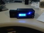
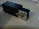
Well Knimrod, you asked for pictures, so I thought i would post a couple. My meter is working very well. My x-100 which is rated by Nova at 122 mW avg, is floating ~117-128 on my DIY meter. One of my DIY red burners measured ~150 mW, which makes sense for the current i'm giving it. I used the RS box you suggested, which was on the small side, and i thought about getting a larger box to make everything, sensor included, but I decided to make it with a detachabe sensor head, and I am starting to like this idea even more. So here is mine.
Attachments
knimrod
0
- Joined
- Nov 4, 2007
- Messages
- 385
- Points
- 0
That's a very cool idea! The best of both worlds.
My personal preference is a detached sensor on a stand/tripod but that's just what I'm used to from years of using a Coherent 210 power meter...
My personal preference is a detached sensor on a stand/tripod but that's just what I'm used to from years of using a Coherent 210 power meter...
IgorT
0
- Joined
- Oct 24, 2007
- Messages
- 4,177
- Points
- 0
I was considering putting the thermopile slightly deeper into the enclosure and / or making a rim around the opening.. This way the reflection would not be so blinding, if you looked at the display from a slightly different angle.chimo said:Very good point. Looks like front/top, front/front or front/external_side.
But i need to see the thermopile, before i can decide on which enclosure to use. Anyone know how big it is exactly, in millimeters?
BTW: Are there any other usefull components on the PCB, except for the thermopile and the IC?
Since it's very big, i asked roSSco to take these two off the board and send only this. The smaller the package, the lower the possibility of our customs opening it up.
Is there anything else in there, that might come in handy?
knimrod
0
- Joined
- Nov 4, 2007
- Messages
- 385
- Points
- 0
I was considering putting the thermopile slightly deeper into the enclosure and / or making a rim around the opening.. This way the reflection would not be so blinding, if you looked at the display from a slightly different angle.IgorT said:[quote author=chimo link=1200112201/315#317 date=1204605772]Very good point. Looks like front/top, front/front or front/external_side.
But i need to see the thermopile, before i can decide on which enclosure to use. Anyone know how big it is exactly, in millimeters?
BTW: Are there any other usefull components on the PCB, except for the thermopile and the IC?
Since it's very big, i asked roSSco to take these two off the board and send only this. The smaller the package, the lower the possibility of our customs opening it up.
Is there anything else in there, that might come in handy?[/quote]
The thermopile is 50 wide (+23 for bnc connector) x 50 tall x 40 deep.
I would also have him remove the cable and connector from the factory PCB. There may be some other small components on there but It's probably not worth sending..
knimrod said:That's a very cool idea! The best of both worlds.
My personal preference is a detached sensor on a stand/tripod but that's just what I'm used to from years of using a Coherent 210 power meter...
I was thinking that, since I have a camera tripod that I could use that. Although i am leary of drilling and tapping a hole in the sensor head. How did you get yours to mount on the tripod?
BTW, as someone mentioned, with the sensor on the same face as the LPM, what you can do is set your digital camera to movie mode (12 second clip is fine) in front of the DPM, so it sees the DPM, turn it on zero it out, aim your laser at the sensor. then you can start your movie clip, and fire your laser while looking away. then you can view the movie clip of your meter readings. (My DMM has a max/avg feature, but I sure like having htis all one unit and the look of the blue DPM is nice)
knimrod
0
- Joined
- Nov 4, 2007
- Messages
- 385
- Points
- 0
desslok said:[quote author=knimrod link=1200112201/315#324 date=1204655657]That's a very cool idea! The best of both worlds.
My personal preference is a detached sensor on a stand/tripod but that's just what I'm used to from years of using a Coherent 210 power meter...
I was thinking that, since I have a camera tripod that I could use that. Although i am leary of drilling and tapping a hole in the sensor head. How did you get yours to mount on the tripod?[/quote]
There is already a 1/4-20 tapped hole in the bottom of the sensor head. That's exactly what you need for a tripod.
I decided to go for a top mount for my sensor. I don't think everything would have fit in the case (esp w/ the 9V batteries in there). I have the sensor pointed to the side so it will be easier to see the DPM when the laser is on the target. I used the existing screw holes in the bottom of the un-anodized part of the sink.
Since my DPM is backlit, I have decided to omit the pilot LED
The mailman has not delivered my blank boards yet, so this unit is still non-functional, however, I used a PCB-sized cutout to assist part placement and layout.
I think I will add a couple of external connectors off the amp output so I will be able to connect it to my DMM and log results on the computer.
knimrod
0
- Joined
- Nov 4, 2007
- Messages
- 385
- Points
- 0
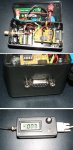
Here's how I integrated my Interface module in the enclosure. I tie-wrapped the two PCBs together with a rubber sheet insulator sandwiched between the boards, bottom-to-bottom. After that it was just routing the wires.. It's a tight fit but it works.. The PC application and the DPM read within 1mW of each other when measuring my 270mW open-can.
Attachments
TheMonk
0
- Joined
- Aug 29, 2007
- Messages
- 750
- Points
- 0
My sensor head is OK it measured 2.28k.TheMonk said:[quote author=TheMonk link=1200112201/255#259 date=1203478480][quote author=knimrod link=1200112201/255#258 date=1203477037]I can't discern anything obviously wrong with your assembled PCB.. I suspect either a problem with your LTC1050, your sensor head/cable, or something unseen relating to the assembly.
The only other thing I can think for you to check is to measure the resistance of the sensor head output (disconnected from amp), with and without the cable. it should measure ~2.3K-2.5K. If it's infinite, there may be a problem there.
If you like, pack it up and send it to me. I'll fix it for ya.
Thanks for the offer to fix it.
 Amk is sending me a LTC1050, I will replace it first and see what happen.
 regards,
TheMonk [/quote]
Knimrod, I sent the DIY board to you to get fix.
Thanks again for your help!
regards,
TheMonk[/quote]
Knimrod, received the Amp board today, thanks for fixing it.
I am so excited, for the first time I am able to messure the Laser optical power. [smiley=evil.gif]
I did some measurement with some of my Lasers.
Dorcy 340mA Open Can with acrylic lens (hole cut out) 125mW, :-/ lens removed 150mW (is this too low for 340mA)
1x AA boost 220mA 16x DL with acrylic lens (hold cut out) 155mW, lens removed 188mW
Leadlight 5mW pot moded 320mA, 15mW
DX 5mW module, 5mW
DX, Target 2mW pointer, 2mW
[smiley=2vrolijk_08.gif]
amkdeath
0
- Joined
- Oct 28, 2007
- Messages
- 2,631
- Points
- 48
My sensor head is OK it measured 2.28k.TheMonk said:[quote author=TheMonk link=1200112201/285#288 date=1203972507][quote author=TheMonk link=1200112201/255#259 date=1203478480][quote author=knimrod link=1200112201/255#258 date=1203477037]I can't discern anything obviously wrong with your assembled PCB.. I suspect either a problem with your LTC1050, your sensor head/cable, or something unseen relating to the assembly.
The only other thing I can think for you to check is to measure the resistance of the sensor head output (disconnected from amp), with and without the cable. it should measure ~2.3K-2.5K. If it's infinite, there may be a problem there.
If you like, pack it up and send it to me. I'll fix it for ya.
Thanks for the offer to fix it.
Amk is sending me a LTC1050, I will replace it first and see what happen. regards,
TheMonk [/quote]
Knimrod, I sent the DIY board to you to get fix.
Thanks again for your help!
regards,
TheMonk[/quote]
Knimrod, received the Amp board today, thanks for fixing it.
I am so excited, for the first time I am able to messure the Laser optical power. [smiley=evil.gif]
I did some measurement with some of my Lasers.
Dorcy 340mA Open Can with acrylic lens (hole cut out) 125mW, :-/ lens removed 150mW (is this too low for 340mA)
1x AA boost 220mA 16x DL with acrylic lens (hold cut out) 155mW, lens removed 188mW
Leadlight 5mW pot moded 320mA, 15mW
DX 5mW module, 5mW
DX, Target 2mW pointer, 2mW
[smiley=2vrolijk_08.gif]
[/quote]
nieieiece
im still debating with myself whether or not to buy an interface module...
knimrod
0
- Joined
- Nov 4, 2007
- Messages
- 385
- Points
- 0
Unfortunately, it looks like someone bought up all the remaining stock of Coherent boards from Lyntec. His Ebay sale is closed and they are no longer available. I'll try and keep the group buy going for one more batch of PCBs but it might be tough now. I'll kick in for a couple more PCBs for myself but 5 more PCBs still need to be sold.
IgorT
0
- Joined
- Oct 24, 2007
- Messages
- 4,177
- Points
- 0
knimrod said:Unfortunately, it looks like someone bought up all the remaining stock of Coherent boards from Lyntec. His Ebay sale is closed and they are no longer available. I'll try and keep the group buy going for one more batch of PCBs but it might be tough now. I'll kick in for a couple more PCBs for myself but 5 more PCBs still need to be sold.
There was a very limited supply from the start.. Luckily roSSco ordered mine in time. (i hope.. there were some delays, i hope it's unrelated)
