TheMonk
0
- Joined
- Aug 29, 2007
- Messages
- 750
- Points
- 0


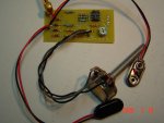
TheMonk said:I powered the board using 2x 9v batteries, and connected the sesor head, but I got 8.2v :-/ at (display out / DMM).
I should be getting ~0v right.
knimrod said:With an output of 8V, the op-amp is saturated. Are you sure you have the -9V supply hooked up? With your voltmeter, verify +9V at U1, pin 7, and -9V at U1, pin 4. Lastly, disconnect the sensor and ground the input. If the op-amp is still saturated, there's an assembly problem or a defective op-amp I think.
knimrod said:[quote author=knimrod link=1200112201/240#241 date=1203363313]With an output of 8V, the op-amp is saturated. Are you sure you have the -9V supply hooked up? With your voltmeter, verify +9V at U1, pin 7, and -9V at U1, pin 4. Lastly, disconnect the sensor and ground the input. If the op-amp is still saturated, there's an assembly problem or a defective op-amp I think.
TheMonk said:[quote author=knimrod link=1200112201/240#243 date=1203368937][quote author=knimrod link=1200112201/240#241 date=1203363313]With an output of 8V, the op-amp is saturated. Are you sure you have the -9V supply hooked up? With your voltmeter, verify +9V at U1, pin 7, and -9V at U1, pin 4. Lastly, disconnect the sensor and ground the input. If the op-amp is still saturated, there's an assembly problem or a defective op-amp I think.
knimrod said:[quote author=TheMonk link=1200112201/240#244 date=1203373541][quote author=knimrod link=1200112201/240#243 date=1203368937][quote author=knimrod link=1200112201/240#241 date=1203363313]With an output of 8V, the op-amp is saturated. Are you sure you have the -9V supply hooked up? With your voltmeter, verify +9V at U1, pin 7, and -9V at U1, pin 4. Lastly, disconnect the sensor and ground the input. If the op-amp is still saturated, there's an assembly problem or a defective op-amp I think.
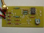
My vr1 = 8.3kLarryQ said:Your Gain Pot seems very far to the Right as well...
Did you follow the formulae and set the Pot before installing>>>
I have built 3 circuits..and never had one even close to that far off of center.
BTW that is the exact Trimmer I used.
Just a thought...
Larry
TheMonk said:[quote author=knimrod link=1200112201/240#245 date=1203375072][quote author=TheMonk link=1200112201/240#244 date=1203373541][quote author=knimrod link=1200112201/240#243 date=1203368937][quote author=knimrod link=1200112201/240#241 date=1203363313]With an output of 8V, the op-amp is saturated. Are you sure you have the -9V supply hooked up? With your voltmeter, verify +9V at U1, pin 7, and -9V at U1, pin 4. Lastly, disconnect the sensor and ground the input. If the op-amp is still saturated, there's an assembly problem or a defective op-amp I think.
TheMonk said:The green resistors were salvaged from the sensor board 5 band resistors.
R1 & R2 =100 ohm Brown+Black+Black+Black+Brwon
R5 = 1 Mega ohm Bronw+Black+Black+Yellow+Brown (it measured 1mega ohm by itself, but on the DIY board it measured 0.3 and 0.5 mega ohm without batteries and I got similar reading while it was on the sensor head board.
R8 = 1k ohm Brown+Black+Black+Brown+Brown.
Kenom said:so ya got another run of the boards for these comin soon?
knimrod said:[quote author=TheMonk link=1200112201/240#247 date=1203375829][quote author=knimrod link=1200112201/240#245 date=1203375072][quote author=TheMonk link=1200112201/240#244 date=1203373541][quote author=knimrod link=1200112201/240#243 date=1203368937][quote author=knimrod link=1200112201/240#241 date=1203363313]With an output of 8V, the op-amp is saturated. Are you sure you have the -9V supply hooked up? With your voltmeter, verify +9V at U1, pin 7, and -9V at U1, pin 4. Lastly, disconnect the sensor and ground the input. If the op-amp is still saturated, there's an assembly problem or a defective op-amp I think.