Welcome to Laser Pointer Forums - discuss green laser pointers, blue laser pointers, and all types of lasers

LPF Donation via Stripe | LPF Donation - Other Methods

Links below open in new window

ArcticMyst Security by Avery

DIY: Laser Power Gauge

Benm

0
Joined
Aug 16, 2007
Messages
7,896
Points
113
For some time i wanted some way to measure laser power, without spending a fortune on a power meter. First off, it is not possible to build something as accurate or reliable as a professional power meter using simple tools, but in this post i'll describe something that can be quite useful in some situations.

Design goal:

- Accuracy within 10% or so
- Simple course calibration
- Materials easily obtained, and inexpensive
- Some handywork and tinkering, but doable with electronics experience

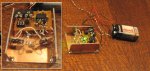
See attached image for electrical schematics (mechanics in next posts).

The principle of operation in sensing the temperature difference between a laser target and ambient, under the assumption that temperature rises linearly with applied laser power. This assumption is fairly reasonable if carefully constructed and operated.

2 ordinary 1n4148 diodes are used to sense tempetures. Such diodes have a nearly linear thermal coefficient of about 2.3 mV/K around room temperature, which is sufficient. The sensing voltages are fed to a 20x differential amplifier, after which 2 pots control gain and offset.

This construction features a heater resistor mounted on the target for calibration. It is constructed such that it does not matter if the resistor or the laser heats the target, but the resistor can be fed a know amount of power to allow calibrating the unit. I included a 100 ohms resistor powerd by either 5 or 2.5 volts, yielding calibration points of 250 and 63 mW respectively.
 

Attachments

  • powergauge_diagram.gif
    powergauge_diagram.gif
    10.2 KB · Views: 1,933


Benm

0
Joined
Aug 16, 2007
Messages
7,896
Points
113
Practical construction:

The sensor is made of a small metal plate, in this case its around 6x5mm, ~0.2 mm thick phosphor bronze from a to-5 star heatsink. You can use copper or aluminium as well, but anodized or otherwise blackened material assures good absorption of laser power. If you have untreated metal, it needs to be blackened by paint or marker pen, but this sacrifices accuracy.

Both the 100R heater resistor and sensing diode are glued onto the back of this place using cyanoacrylate (or thermal adhesive). Make sure the resistor and diode dont touch eachother, so all thermal contact is via the metal plate. The component leads are about half an inch long and soldered to the casing made out of copper-clad pcb material. I scraped some away to make electrically isolated pads for mounting and contact, see picture too.
 

Attachments

  • powergauge1.jpg
    powergauge1.jpg
    505.5 KB · Views: 1,233

Benm

0
Joined
Aug 16, 2007
Messages
7,896
Points
113
Picture of the whole setup:

Powered by a 9v battery, its good to go.

Calibration is performed by turning the unit on, adjusting the gain about half way, and setting the readout to 0 using the offset pot. Now, select the 250 mW calibration point, and wait for a minute. Adjust the gain pot such that the meter reads 250 mW. The pots are slightly interdependent, so after removing the calibration current and waiting some time, offset may require slight adjustment. Results can be verified at the 63 mW setting, and should be consistent within a mW or 2.

Obviously you can construct something similar in many forms, i used what i had available here at the moment.
 

Attachments

  • powergauge2.jpg
    powergauge2.jpg
    360.7 KB · Views: 782

Benm

0
Joined
Aug 16, 2007
Messages
7,896
Points
113
Results:

First of all, this power meter is very slow. Taking a reading takes around 30 seconds to stabilize. All thermal meters suffer from this problem, but proper thermopiles are faster, and most use microcontroller readouts with prediction that make them appear to be much faster.

Some measurements:

- calibation and set as described above, 250mW heating -> 250 mV
- verification of 63 mW heating -> 67 mV (offset was corrected after this)
- DX200 red, running 2x3.0v cells -> 168 mV **
- CR2 powered '50 mW' green -> 60 mV (this laser is quite temperature dependant)
- KD 'edwina' CR2 green (rated 50 mW) -> 22 mV (this one is underpowerd, i knew as much)
- 16x sony diode @ 210 mA in MXDL -> 147 mV

And, with the heater on and the DX200 on the target, it reads 423 mV (which accounts for 250 mW heating, power by the laser: 173 mV) **

** as you can see, results are quite consistant over the range, even at 423 mW observed power.
 
Joined
Mar 2, 2008
Messages
1,500
Points
0
Do you have a Verified laser power meter that you can use to calibrate this design you have ?
 

Benm

0
Joined
Aug 16, 2007
Messages
7,896
Points
113
Unfortunately, no. I'll try to set up a comparison though, since i'm quite interested how well it actually works myself... either using a side-by-side test or using a laser of known power (we chould send a DX200 around or something). But dont expect anything better than a few percent in any case.
 
Joined
Nov 2, 2008
Messages
51
Points
0
I'm interested to throw one of these together due to the recent decline in exchange rate, an LPM becomes a very expensive tool for this hobby.. however i'm a little confused by your schematic (probably my bad so please don't flame).

I'm not sure where the pins connected near the ones labeled 5,6,7 going vertically are from/to? Sorry if this is a stupid question !

Thanks for posting this up.


EDIT: Also does it matter if the heater resistor is a 0.5w or a 1.0watt rated resistor? Yours looks like a 1 watt in the pics, but not sure! I have plenty of 0.5w resistors, but will have to buy if a 1.0watt is required (not a problem, just wanted to know). Thanks.
 

Benm

0
Joined
Aug 16, 2007
Messages
7,896
Points
113
The schematic is a bit confusing due to the software i used to draw it. Both opamps are in a single IC, TL072. The 5,6,7 pins are for the second half of the opamp, you can forget the power lines there since they are already drawn in the first opamp (pins 4 and 8).

The heater resistor I used is a 0.25 watt, which is sufficient. I really dont recommend using a bigger one because of its thermal capacity which would make the meter even slower. Btw, the 0.25 watt carbon resistor i used is about the same size as a 400 mW metal film resistor, which would be fine.
 

Benm

0
Joined
Aug 16, 2007
Messages
7,896
Points
113
Oh well, it is a bit of a build for people with limited electronics experience.

Good news on the accuracy testing part: One of the forum members will test a DX200 laser on a proper power meter at a couple of voltages/currents, and then send the results and the laser to me.

I'll duplicate these measurements with the meter calibrted as described and post the results here... might take some time to get the reference here and measurements performed, but it should give some more insight into the abilities of this simple circuit.
 

Benm

0
Joined
Aug 16, 2007
Messages
7,896
Points
113
I dont think so - It is more a thing for when you want to spend more time than money. Building them commercially would probably not be viable, since it takes some handywork to put together, and there are more accurate alternatives on the market for a few 100 bucks.

Perhaps it would be possible to simplify the sensor design so it's on the actual circuit board, i wonder what results other builders get from this.

LPF member LikeitBright has kindly measured (using professional kit) the output power of a DX200 at serveral voltages and currents for me, that laser is now en route here. I'll post the results against that laser at known power levels here once available.


Top