Welcome to Laser Pointer Forums - discuss green laser pointers, blue laser pointers, and all types of lasers

LPF Donation via Stripe | LPF Donation - Other Methods

Links below open in new window

ArcticMyst Security by Avery

DIY: Laser Power Gauge

Joined
Dec 27, 2008
Messages
38
Points
0
I've just finished putting togheter my assembly, results are getting even better than yesterday on a non-ventilated area. Also the 60mW measurements are showing expected results and no major fluctuations are noticed.


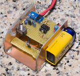
if you're planning to build this circuit, don't expect to have it running well on an open-air build. Any even little casual air flow near the sensor (like your open hand moving quicky near it) may cause your results to become unstable, especially on low imput powers. It's strongly reccomended to build at least a little pcb-made box to avoid too much air to impact on the sensor and worsen its stability.

Is there anyone else who can try this circuit on a known-power laser? I'm waiting for my DX200, I'm curious to see if we're getting over-estimated power measurements or it comes how much near to the laser estimated power :)


Joined
Dec 27, 2008
Messages
38
Points
0
It's really easy to build, just take care of the setup to avoid sensor instability / oscillation. If you're planning to use this for some time, it's really reccomended to run off a 6xAA rechargeable pack, my circuit is eating cheap 9V packs at an unbearable speed :) measured 12.5mA idle current, 37.5mA heating low and 62.5mA heating high, off a cheap 9V pack you would last not so long ;D

here's my final build:


I've replaced the pcb board with the sensor with some better screw-contacts to put any kind of sensor in, getting also a far better stability.
 

Benm

0
Joined
Aug 16, 2007
Messages
7,896
Points
113
@Andrea87,

Very nice construction you have there, it does need a bit of a box to get stable results... airflow from convection from the warm sensor is fine, but a bit of outside wind will throw off results.

As for battery consumption: i didnt design it to be energy efficient in any way, and your current measurements seem right. You can run this circuit of a 9v wall adapter if you like, and it also works well from 8.4v rechargeable (nimh) batteries... even 7.2v could work if you have a good 78L05. For 9V batteries: its probably best to use alkaline cells, the really cheap kind hardly has any charge to begin with.
 
Joined
Jun 30, 2008
Messages
286
Points
0
And i can make the easyest part, a the microcontroller one. Using a PIC AD module and controlling an LCD to display the mW. Not hard to do and would make it professional for about 6 bucks more. (can also use 7segment displays)

Just needs a bit more amplification :p

I'll tell you if i do it.
 

Benm

0
Joined
Aug 16, 2007
Messages
7,896
Points
113
I've considered doing something like that - using the adc in a 16f877 or a similar chip. There is defenitely room to improve results using a microcontroller here, such as reducing the time to stabilize and employing a balanced measurement with an indentical unlit sensor.

If you make something using a uC i'd be interested, as i have the things to do pic development here. I didn't want to employ it in this circuit for the broader public though as it does require some development tools (programmer and such) and complicates reconstruction a bit. Please do post any results though!
 

Warske

0
Joined
Mar 10, 2009
Messages
145
Points
0
Benm said:
I am a bit puzzled why the results are too high, i expected them to be too low due to light not being absorbed and all. Somehow the laser seems to do a better job at heating the sensor than the resistor does... perhaps a matter of mechanical design.
First, very interesting thread!  Great job!

As I mentioned on another thread, I have two ideas about why the results might be too high.

The first idea is a bit complicated to explain.  To help with that I made a very simplified thermal model of your sensor, neglecting convection and radiation losses, and concentrating on the leads of the diode and resistor (see pic).

In the thermal model
- temperature is modeled as voltage
- thermal power is modeled as current
- thermal resistance is modeled as resistance

Assume the metal plate has zero thermal resistance.

Id - the power from the laser diode that is absorbed and converted to heat.  Some power is reflected, so your meter should read low.  To simplify, assume all the power is absorbed.

Ir - the power from the 0.25 W resistor.

Vout - the temperature of the diode junction, which generates your output reading.

RDC - the thermal resistance from the diode junction to the metal plate (through the Diode Case).

RDW - the thermal resistance from the diode junction to ambient (through the Diode Wires).

RRC - the thermal resistance from the resistor junction to the metal plate (through the Resistor Case).

RRW - the thermal resistance from the resistor junction to ambient (through the Resistor Wires).

Now, what we hope will happen is that if we apply laser power to the black surface of the metal plate, or we apply the same amount of electrical power to the resistor, each will give us the same temperature rise above ambient at the diode junction.

To test this with the thermal model, assume initially that each resistor is 1 ohm.
If we apply 1 amp of current at Id (modeling the laser), then Vout will be 0.5 v.
If we apply 1 amp of current at Ir (modeling the power from the resistor), then Vout will be 0.25 v.
So we would actually have to have twice as much current at Ir as at Id to match the Vout.
We see that, if the model is correct, the laser power is overestimated.  Since we don't actually know the real value of the resistances, we don't know exactly how big this effect is.

The thermal model also tells you that for Vout to be the same when each input is the same, then RRC must be zero and RRW must be infinite.

The first means that you get improvement if you have better thermal coupling between the carbon film resistance element and the metal plate.  So, for example, a 1 W surface mount resistor would likely give you better coupling, since it is thin and flat and there is no case material to separate it from the metal plate.    eg: http://search.digikey.com/scripts/DkSearch/dksus.dll?Detail&name=PT100AFCT-ND  While this should be an improvement, it is still not perfect.

The second means that you get improvement if you increase the thermal resistance of the resistor leads by using much thinner wire.  Note that this doesn't apply to the leads on the diode.  You can also use thermally conductive epoxy to cement these thinner leads to the metal plate.  This changes the thermal model in a favorable way.

If you increase the thermal resistance of your resistor leads, your thermal time constant will increase, which you mentioned in a previous post as being undesirable.  You can reduce the time constant again by attaching similar leads directly to the metal plate using thermally conductive epoxy.

There are still effects due to radiation and conduction losses which make the situation imperfect, but the above should be an improvement.

The second idea is that I didn't see where you account for the temperature coefficient of the heater
resistor.  As it heats up, its resistance will increase and it will provide less power than expected based on just the voltage across it.  But I may have missed where that is accounted for.

This looks like a great project which gives very useful measurements.
 

Attachments

  • thermal_model.jpg
    thermal_model.jpg
    17.9 KB · Views: 231

Benm

0
Joined
Aug 16, 2007
Messages
7,896
Points
113
Thanks for your idea's.

I suppose the thermal resistance theory has merit, though its hard to actually measure any of it. I could try a flat SMD resistor as the heater to see if it makes any difference, though i dont have any on hand right now.

Warske said:
If you increase the thermal resistance of your resistor leads, your thermal time constant will increase, which you mentioned in a previous post as being undesirable.  You can reduce the time constant again by attaching similar leads directly to the metal plate using thermally conductive epoxy.

I have considered extending the extra-leads approach so far as to use a metal strip instead of a small target. Either side of the strip would function as a (low) thermal resistor taking heat away from the sensor. As a concept, this would work well, but in practice it results in thermal resistances so low it becomes impossible to measure the small temperature rise with the diode sensors.

The device pictured is something that seems to work optimally for me: more insulation makes it even slower, more thermal conduction makes the temperature differences too small to measure well... perhaps the latter can be remedied using proper temp sensors instead of diodes.

Warske said:
The second idea is that I didn't see where you account for the temperature coefficient of the heater
resistor.  As it heats up, its resistance will increase and it will provide less power than expected based on just the voltage across it.  But I may have missed where that is accounted for.

Good idea, but doesnt apply here: the heater is a carbon film resistor which have a negative thermal coefficient. Still, resistors are all made to have fairly low thermal coefficients, and i much doubt a 10 degree warm up would shift their resistance by more than 1% in either direction worst-case.

I think your idea of the heater resistor losing more heat through its leads when in operation than under external (laser) heating is very plausible. I am still quite happy with accuracy within 10% though, which was the goal to begin with.

At the moment i am mainly interested in speeding it up - i trust the measurements, but spending a few minutes on calibration and a minute or so on every measurement becomes tiresome. Then again, i guess it is an overall success considering i built it with junkbox and stock components and it seems reproducible for others as well.
 

Warske

0
Joined
Mar 10, 2009
Messages
145
Points
0
Benm said:
I could try a flat SMD resistor as the heater to see if it makes any difference, though i dont have any on hand right now.
I'm happy to send you one, gratis, if you live in the USA (not sure how much it costs to ship outside).  Just PM me an address.

At the moment i am mainly interested in speeding it up ...
I found your discussion about this here: http://www.laserpointerforums.com/forums/YaBB.pl?num=1234443192/0#29
and from what you say, the sensor acts as a single pole low pass filter ("a capacitor charging from a resistor").

I read that commercial thermopile based LPMs just use an electrical high pass filter between the sensor and the readout.

So the idea is to use a high pass filter with a zero at the same frequency as the low pass filter pole to cancel it.  http://www.google.com/search?hl=en&q=pole+zero+bode+analysis&aq=f&oq=

I haven't actually tried this for a laser power meter, but it might give you an idea.
 

Benm

0
Joined
Aug 16, 2007
Messages
7,896
Points
113
I've done some experiments approximating the final reading, but noise has been a major problem witht that... theory looks very good on paper, but taking real measurements it seems less straightforward. I dont have much experience with uCs handling such data though, so there could be some tricks i have no clue about that can solve the problem.

As far as sending components go: i live in europe, but it should not be that expensive if you put it in an ordinary letter envelope. I believe postage from the us is $1.02 or $1.20 for a <20 gram envelope, and resistors are sturdy enough to survive a trip like that. If you have any 100 ohms resistors in a usable form factor (1206?) i'd be happy to give those a go.
 

Warske

0
Joined
Mar 10, 2009
Messages
145
Points
0
With noise a problem, a high pass filter will probably just make it worse.

The 1206 size resistors are 1/4 W, which I don't have, sorry. I have a few of those digikey 1 W resistors I mentioned in a previous post. These are 2512 size for the higher power. Same thickness as 1206 at 0.60, but the length and width dimensions are larger (6.40 x 3.20) for lower thermal resistance to your metal plate. Still smaller than the 1/4 W resistor with leads that you used, I think. Happy to send one to you in europe.
 

Benm

0
Joined
Aug 16, 2007
Messages
7,896
Points
113
I could try with the 2512 size, though i am not sure how it will affect the thermal capacity of the whole sensor and what that will do to response times. I suppose the only way to find out is to give it a try though.... i'll pm you the details!
 

Warske

0
Joined
Mar 10, 2009
Messages
145
Points
0
I sent it out just now First Class Mail International.

I also included some thin black anodized aluminum that is designed to absorb light and IR, which I'm evaluating for the Warske Standard Laser Target, Mark II ;)

It should be more black than the heat sinks you are using.
 

Benm

0
Joined
Aug 16, 2007
Messages
7,896
Points
113
Sounds awesome, thanks!

The anodized targets are probably better, the ones i'm using look like phosphor bronze with a thin black powdercoat of sorts - still appear very black to the eye, but i'm sure its not perfect.


Top