Welcome to Laser Pointer Forums - discuss green laser pointers, blue laser pointers, and all types of lasers

LPF Donation via Stripe | LPF Donation - Other Methods

Links below open in new window

ArcticMyst Security by Avery

DIY Homemade laser diode driver

Status
Not open for further replies.

anselm

0
Joined
Nov 22, 2010
Messages
2,448
Points
0
I'm just chiming in here to tell you guys, that as of recently and as a consequence of
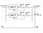
this thread, I am using two LM317
in parallel
, each one with it's own independent adjustable resistor for current control, and they both behave fine.:)
Otherwise I have it just the same like on rhd's diagram, with input and output pins parallel'd together.
I do have a hefty 16V 1000uF capacitor on the output, I don't know if that is
key for the stability, since it has always been there.!
On the input side, I even have a 16V 2200uF cap.:D
Overkill much? When I turn off the laser, it keeps glowing dimly for almost a minute.:D:D

One problem I am having though: each LM317 on it's own is able to provide about 1.2A
with the resistors I am using, but I cannot seem to get the combined output to more
than ~1.6A. It's probably better for the diode anyway that it doesn't go higher!:p
Might be a battery issue....

I'll look into that when I add the capabilty of connecting a line transformer 12V 2A...


HIMNL9

0
Joined
May 26, 2009
Messages
5,318
Points
0
I disagree, even in the same production lot there can be variations in the voltage drop it regulates for, if one regulates for 1.24 volts and the other for 1.26, only one will take all the load if they are connected with all pins together.
Putting votlage sources parallel is indeed a bad idea, but they are wired as a current source which does work in parallel. The LM317 regulates it output pin, which is not directly connected to the other output pin, so the changes of one regulator won't affect the other much, certainly if the load is a diode. A larger capacitor will be enough to keep it stable. I can do this when I get home to see how stable it is.

True about the tolerances, anyway, directly paralleling is always working better if done totally, instead than with independent regulations, and if the components are from the same production lot, it may cause very few problems, for 2 regulators in parallel (more than 2, it's a different thing)

Anyway, being "picky", the better system will be to use "decoupling" resistors, but it's difficult to find half watt 0.02 to 0.05 ohm resistors (at least, it's difficult here), so i suggested to try the direct paralleling of the 2 ICs (it's a solution that i have already used a lot of times, with 2 units, without too much problems) .... it's still possible to improve this situation adding the decoupling resistors, if they can be found easily in your country.


@ Anselm: About the current, no, you can't expect the double of the current using them independently (also using them paralleled directly, but in that way you can still get some more current) ..... also, remember that these regulators was not specifically planned for be used as current regulators ..... LM series was specifically designed as VOLTAGE regulators, and also in the way we use them, they still regulate the voltage (they, in fact, change the output voltage for keep the reference voltage always the same, and we can use them as current regulators only cause we derive the reference voltage from a resistor in serie with the load, and this is depending from the current through it) ..... the "1.5A max" limit that you read on some datasheets, is not the maximum regulated current in current mode, is the maximum current that the device can hold in voltage mode ;)
 

rhd

0
Joined
Dec 7, 2010
Messages
8,475
Points
0
anselm:
I'm glad to hear that my circuit layout is working for YOU :) It hasn't been too awesome for me.

I'll mention a few of the conclusions I've come to:

1) The design is not nearly as reliable with 2x LM1117s paralleled similarly.
2) As you've picked up on, it doesn't actually "unlock" double the current. I similarly have had trouble exceeding 1.6A or so. I've even tried 2x 18650 in parallel with another 2x18650 (in other words, plenty of available input current). No dice.

I've come to the following conclusion:

- LM338T is the way to go for 445nm diodes. Handling up to 5A current. Their 2.5V voltage dropout is fine:
---- 445nm diodes don't have a VF that will exceed 5V
---- So, 5V + 2.5V = 7.5V. I'm cool with keeping my batteries fully charged
http://laserpointerforums.com/f65/3x-445nm-ld-piv-plot-53927.html#post758940

- LM1117 is the way to go for 12x 405nm diodes. Handling a max of 800mA current. Their < 1V voltage dropout is awesome:
---- 405nm 12x diodes don't exceed the 800mA current limit of a single 1x LM1117
---- Their VF is a lot higher than a 405nm diode, but the 6V + 1V = 7V is perfect.
http://laserpointerforums.com/f51/pioneer-12x-blu-ray-bdr-205-a-44607-12.html#post617026

- LM1117 is probably also the way to go for RED diodes. They'll probably allow for single cell builds.
---- You might be able to squeeze out a RED build on 1x cell.
---- 4.2V (charged cell) - 1V (or lower) voltage drop = ~3.2V available for a RED diode. That's just about right for a 400mA LOC diode.
http://laserpointerforums.com/f50/question-about-lpc-815-loc-forward-voltage-46572.html#post631700

YMMV
 
Last edited:

anselm

0
Joined
Nov 22, 2010
Messages
2,448
Points
0
This issue of paralleling LM317 is leaving me no rest.
This guy on laserfreak.net apparently drives high amp, fiber-coupled IR diodes with as much as
4 or 5 LM317s in parallel.
Laser Cutter Notes - RepRapWiki

Gosh I feel so dumb, like a tinkerer toying around with stuff he doesn't really understand.:eek:

Maybe the trick are those balancing resistors on the output of each IC....
550px-LM317-12V_Nx1A.jpg

Hmm, back to the breadboard I must go.:D
I'll get it right, eventually.
 

rhd

0
Joined
Dec 7, 2010
Messages
8,475
Points
0
Keep me updated :)

I'll experiment a bit more this week too. Right now, I need to wait for some 445s to arrive, then I'll unpack my tinkering gear again.
 

HIMNL9

0
Joined
May 26, 2009
Messages
5,318
Points
0
@ rhd: don't forgot the dropout on the resistor ..... 5V + 2.5V + 1.25V = 8.75V ..... ;)


@ anselm: right that, i was saying ..... decoupling resistors can solve the problem of the direct paralleling (also if is still better a single current resistor configuration) ..... anyway, if attention is paid in setting all the regulators at the identical current, also this schematic can work (also, 0.1 ohm decoupling resistors works good, too, dissipating less power in heat)
 

rhd

0
Joined
Dec 7, 2010
Messages
8,475
Points
0
I believe the resistor is already factored in to the 2.5 - 3 volt drop of an LM317 circuit, no?
 

rhd

0
Joined
Dec 7, 2010
Messages
8,475
Points
0
I couldn't come up with anything in my searching - but does anyone remember a dual LM317 setup being implemented in a build thread anywhere here previously?
 

rhd

0
Joined
Dec 7, 2010
Messages
8,475
Points
0
In about 2 hours, I'm going to give the following a shot, with the intention of trying to achieve ~1.8 to 1.9 amps output:

(any suggested tweaks are welcome)

attachment.php
 

Attachments

  • rhd1.jpg
    rhd1.jpg
    45.5 KB · Views: 7,435

jib77

0
Joined
Jun 19, 2010
Messages
718
Points
0
This driver is based on a LD1085 LDO regulator from ST Micro. Dropout is only 1.5V and can deliver 3A!

With 8V input and 4V load, I took it to 1.8A Iout before my bench PSU decided to shutdown (its max is 2A). It was cool to the touch. Ill try 2x26650 IMRs as soon as I find a suitable battery holder. This driver has 0.5ohm 4W set resistance for theoretical 2.5A.

Of course lots of heatsinking required:
 

rhd

0
Joined
Dec 7, 2010
Messages
8,475
Points
0
jib77: That's fantastic! Can we expect an update to your LM1117 fixed drivers?

anselm: My design is hitting 1.74 A with a 4V test load simulation, and 1.65 A with a 5V. In both cases, using 2x 16340s.

I'm going to try with 18650s, and then modify the resistor to 1 Ohm instead of 1.33 ohm, to see if the output increases.
 

rhd

0
Joined
Dec 7, 2010
Messages
8,475
Points
0
anselm, my results:

1) The cell does NOT appear to be the limiting factor. I tried 2 sets of 18650s and 1 set of 16340s, in all cases the limits were the same.

However, adjusting the resistor values had the effect I was seeking - more amperage! However, the math doesn't hold up - or at least my math isn't good enough to recognize the formula.

At 1.36 ohms:
- 1.65 A output (5V simulated diode)

At 1 ohm (otherwise same circuit as diagram):
- 1.80 A output (5V simulated diode)

At 0.68 ohms (otherwise same circuit as diagram):
- 1.92 A output (5V simulated diode)

So I've achieved what I wanted, but can't explain why, or how the math works.

Next I'm going to hook this up to a real 445nm (at the 1.8A output) and check the results.
 

jib77

0
Joined
Jun 19, 2010
Messages
718
Points
0
Can you post some pics of your setup?

re: my LM117 driver ... no, this chip requires 2X more copper area in the PCB, so it would have to use a new design. The PCB in above pic was a failed LM1117 w/ pot, its 2x the size of my current pot-less driver.

anselm, my results:

1) The cell does NOT appear to be the limiting factor. I tried 2 sets of 18650s and 1 set of 16340s, in all cases the limits were the same.

However, adjusting the resistor values had the effect I was seeking - more amperage! However, the math doesn't hold up - or at least my math isn't good enough to recognize the formula.

At 1.36 ohms:
- 1.65 A output (5V simulated diode)

At 1 ohm (otherwise same circuit as diagram):
- 1.80 A output (5V simulated diode)

At 0.68 ohms (otherwise same circuit as diagram):
- 1.92 A output (5V simulated diode)

So I've achieved what I wanted, but can't explain why, or how the math works.

Next I'm going to hook this up to a real 445nm (at the 1.8A output) and check the results.
 
Last edited:

rhd

0
Joined
Dec 7, 2010
Messages
8,475
Points
0
Jib - I'll do so if you want - but the actual LM317 portion is so small that you might not be able to make sense of it visually (IE, I didn't use a breadboard)

Another update:
- with a real 445nm diode, I had to take the resistors back down to 0.68 ohms in order to get 1.74 A output into the diode.
 

rhd

0
Joined
Dec 7, 2010
Messages
8,475
Points
0
You know what - this is a garbage endeavor :)

All I was accomplishing was overshooting the resistor value to try and push the setup further, without any logic behind it.

That approach doesn't make any sense. You don't end up with a constant current driver. You end up with a kludge that jumps around a lot without any discernible pattern. For some reason, 3x 10440s was able to use the same setup and produce 2.4 A, while 2x 16340s produced 1.6 A.

Why? The available current from a 10440 is surely lower. The additional voltage was not required by my test load. If anything, the LM317s were working overtime dissipating the voltage as heat.... which explains why after 20 second with the 3x 10440s, the current started crashing, right down to zero (I presume the LM317s had thermal protection kick in).

Anyway, the nutshell conclusion here - I've ordered LM338s. It's not worth trying to combine LM317s. Just isn't worth the aggravation.
 
Status
Not open for further replies.


Top